ANTI-LOCK BRAKES
Anti-lock Brake Wiring Diagrams for Infiniti J30 1996
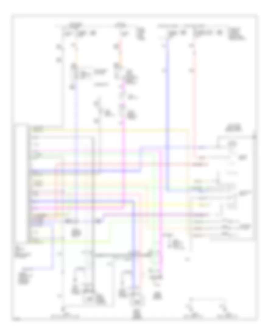
List of elements for Anti-lock Brake Wiring Diagrams for Infiniti J30 1996:
- (1995) (1996)
- (bottom left "c" pillar)
- (left side of i/p)
- (right rear
- (right shock tower)
- (right side of i/p)
- Abs control
- Abs warning ind.
- Actuator
- Actuator relay
- All times
- Alternator
- Check connector (left of steering column)
- Engine compt)
- Fuse 20 7.5a
- Fuse 30 fuse 31 7.5a
- Fuse 4 15a
- Fuse 47 fuse 57 20a
- Fuse and fusible link box (right side engine compt)
- Fuse block (left kick panel)
- Fusible link e fusible link c 30a
- G102 left shock tower)
- G103
- G201
- G202
- G904
- G905 (bottom right "c" pillar)
- Hot at
- Hot at all times
- Hot in run or start
- Instrument cluster
- J/c-10 (behind center of i/p)
- J/c-13 (right rear of trunk)
- J/c-6 (left i/p)
- J/c-7 (1995) (left i/p)
- Left front wheel sensor
- Motor
- Motor relay
- Nca
- Pnk
- Rear wheel sensor
- Red
- Right front wheel sensor
- Solenoid valves
- Stop lamp switch (on brake pedal support)
- Unit (center rear of trunk)
 English