ANTI-LOCK BRAKES
Anti-lock Brakes Wiring Diagram (1 of 2) for Infiniti Q45 2005

List of elements for Anti-lock Brakes Wiring Diagram (1 of 2) for Infiniti Q45 2005:
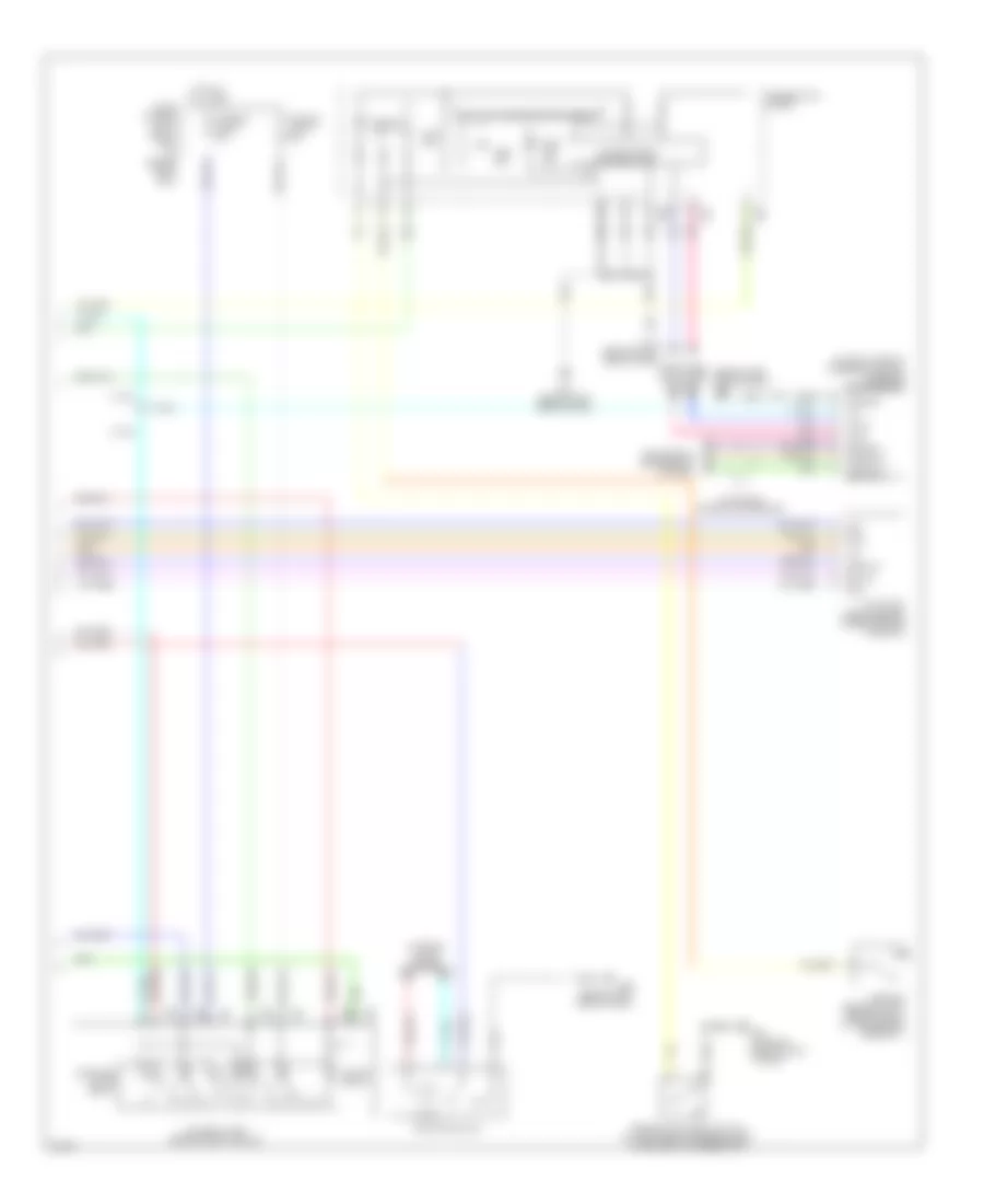
Anti-lock Brakes Wiring Diagram (2 of 2) for Infiniti Q45 2005
List of elements for Anti-lock Brakes Wiring Diagram (2 of 2) for Infiniti Q45 2005: