ANTI-LOCK BRAKES
Anti-lock Brakes Wiring Diagram, with Traction Control for Isuzu Ascender Limited 2005

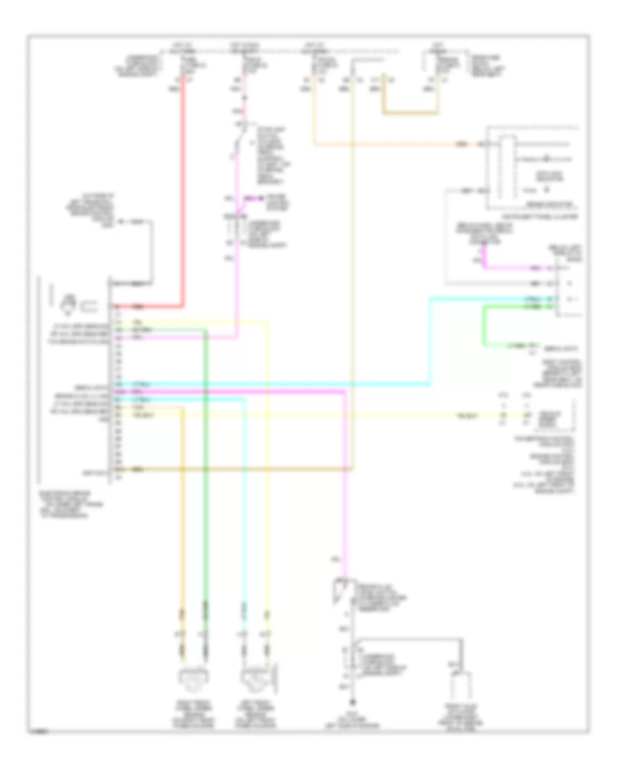
List of elements for Anti-lock Brakes Wiring Diagram, with Traction Control for Isuzu Ascender Limited 2005:
- (below dash, above accelerator pedal) data link connector
- 4.2l
- 5.3l
- Abs fuse 33 60a
- Abs pump
- Anti-lock indicator
- Automatic a/c
- B10
- Body control module (bcm) (beneath left rear seat, on rear fuse block)
- Brake fluid level switch (in brake master cylinder fluid reservoir)
- Brake fluid lvl sig
- Brake fuse 51 10a
- Brake indicator
- C11
- Cruise control system
- Delivered torque sig
- Delivered torque signal
- Electronic brake control module (on inner left frame rail, adjacent to transmission)
- Front axle actuator (lower right front of engine, on oil pan)
- G107 (on lower left side of engine)
- G201
- G304 (outside of left frame rail, near electronic brake control module)
- Hot at all times
- Hot in run
- Hot in run or start
- Hvac 1 fuse 39 10a
- Ign e fuse 22 10a
- Ignition 3
- Illum
- Instrument panel cluster
- Interior lights system
- Ipc/dic fuse 24 10a
- Left front wheel speed sensor (on left front wheelhousing)
- Lf whl spd sens ref
- Lf whl spd sens sig
- Low trac indicator
- Manual a/c
- Pnk
- Powertrain control module (pcm) (4.2l) engine control module (ecm) (5.3l) (4.2l: on left front of engine) (5.3l: on left front of engine compt)
- Rear fuse block (below left rear seat)
- Red
- Requested torque sig
- Requested torque signal
- Rf whl spd sens ref
- Rf whl spd sens sig
- Right front wheel speed sensor (on right front wheelhousing)
- Serial data
- Sp201 (lower right center of dash)
- Sp205 (below left side of i/p)
- Stoplamp switch (w/o eap: on brake pedal support) (w/ eap: top of brake pedal bracket)
- Tan
- Tcc brake switch sig
- Trac active telltale
- Trac ctrl sig
- Traction control switch
- Traction disable sw
- Traction disable switch
- Traction off indicator
- Underhood fuse block (on left side of engine compt)
- Vehicle speed signal
- Vss
Anti-lock Brakes Wiring Diagram, without Traction Control for Isuzu Ascender Limited 2005
List of elements for Anti-lock Brakes Wiring Diagram, without Traction Control for Isuzu Ascender Limited 2005:
- (below dash, above accelerator pedal) data link connector
- (below left side of i/p)
- (on inner left frame
- (outside of left frame rail, near electronic brake control module) g304
- 4.2l
- 5.3l
- A10
- Abs fuse 33 60a
- Abs pump
- Anti-lock indicator
- B10
- Body control module (bcm) (beneath left rear seat, on rear fuse block)
- Brake fluid level switch (in brake master cylinder fluid reservoir)
- Brake fluid lvl sig
- Brake fuse 51 10a
- Brake indicator
- C11
- Control module
- Cruise control system
- Electronic brake
- Front axle actuator (lower right front of engine, on oil pan)
- G107 (on lower left side of engine)
- Hot at all times
- Hot in run
- Hot in run or start
- Ign e fuse 22 10a
- Ignition 3
- Instrument panel cluster
- Ipc/dic fuse 24 10a
- Left front wheel speed sensor (on left front wheelhousing)
- Lf whl spd sens sig
- Pnk
- Powertrain control module (pcm) (4.2l) engine control module (ecm) (5.3l) (4.2l: on left front of engine) (5.3l: on left front of engine compt)
- Rail, adjacent
- Rear fuse block (below left rear seat)
- Red
- Rf whl spd sens ref
- Right front wheel speed sensor (on right front wheelhousing)
- Serial data
- Sp205
- Stoplamp switch (w/o eap: on brake pedal support) (w/ eap: top of brake pedal bracket)
- Tan
- Tcc brake switch sig
- To transmission)
- Underhood fuse block (on left side of engine compt)
- Vehicle speed signal
- Vss