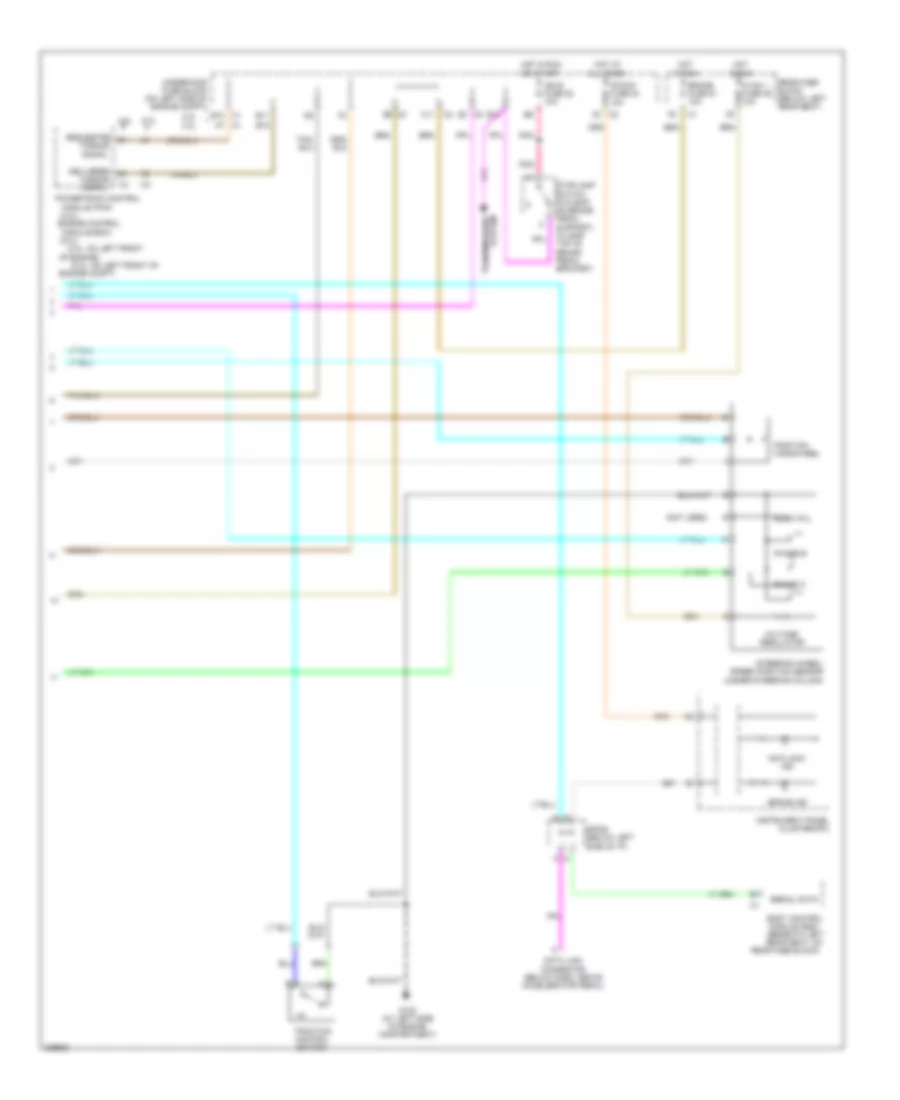
ANTI-LOCK BRAKES
Anti-lock Brakes Wiring Diagram (1 of 2) for Isuzu Ascender LS 2006

List of elements for Anti-lock Brakes Wiring Diagram (1 of 2) for Isuzu Ascender LS 2006:
- (in brake master
- (on left side of
- 5v ref
- Abs fuse 33 60a
- Abs pump
- Brake fluid
- Class 2 serial data
- Cylinder fluid
- Electronic brake control module (on inner left frame rail, adjacent to transmission)
- Engine compt)
- G107 (4.2l: on lower left side of engine) (5.3l: lower left side of engine)
- G304 (outside of left frame rail, near electronic brake control module)
- Gnd
- Hot at all times
- Ignition 3 voltage
- Left front wheel speed sensor (on left front wheelhousing)
- Left rear wheel speed sensor (in left rear wheelwell)
- Level switch
- Low ref
- Nca
- Red
- Reservoir)
- Right front wheel speed sensor (on right front wheelhousing)
- Right rear wheel speed sensor (in right rear wheelwell)
- Sens sig
- Sig
- Signal 1
- Signal 2
- Signal a
- Signal b
- Switch sig
- System
- Tan
- Transmissions
- Underhood fuse block
- Underhood fuse block (on left side of engine compt)
- Vses fuse 58 (4.2l) vses fuse 61 (5.3l) 60a
- Yaw rate & lateral acceleration sensor (under front passenger's seat)
- Yaw ring rast ctrl
- Yaw ring rastctrl
Anti-lock Brakes Wiring Diagram (2 of 2) for Isuzu Ascender LS 2006
List of elements for Anti-lock Brakes Wiring Diagram (2 of 2) for Isuzu Ascender LS 2006:
- (4.2l)
- (4.2l: on left front
- (5.3l)
- (5.3l: on left front of
- (not used)
- 4.2l
- 4.2l 5.3l
- 5.3l
- Anti-lock ind
- B10
- B11
- Body control module (bcm) (beneath left rear seat, on
- Brake fuse 51 10a
- Brake ind
- C1 a7
- C1 b10
- C11
- Data link connector (below dash, above accelerator pedal)
- Delivered
- Engine compt)
- Engine control
- G102 (at left side of engine compartment)
- Hot at all times
- Hot in run
- Hot in run or start
- Hvac 1 fuse 39 10a
- Ign e fuse 22 10a
- Index pul
- Instrument panel cluster(ipc)
- Ipc/dic fuse 24 10a
- Module (ecm)
- Module (pcm)
- Of engine)
- Phase a
- Phase b
- Pnk
- Position handwheel
- Powertrain control
- Rear fuse block (below left rear seat)
- Rear fuse block)
- Requested
- Serial data
- Sp205 (below left side of i/p)
- Steering wheel/ speed position sensor (under steering column)
- Stoplamp switch (w/o eap: on brake pedal support) (w/ eap: top of brake pedal bracket)
- Torque signal
- Traction control switch
- Transmissions system
- Underhood fuse block (on left side of engine compt)
- Voltage regulator