ANTI-LOCK BRAKES
Anti-lock Brake Wiring Diagrams for Isuzu Pickup S 1995
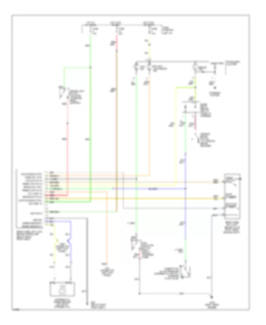
List of elements for Anti-lock Brake Wiring Diagrams for Isuzu Pickup S 1995:
- (at parking
- (below right front seat)
- (left i/p)
- (mounted on brake
- 4wd ind.
- 4wd indicator switch (right side of transfer case)
- 4wd switch in
- Battery in
- Brake
- Brake ind.
- Brake ind. ctrl
- Brake light
- Brake switch
- Brake switch in
- Brake valve (right rear
- Charging system
- Combination valve pressure differential switch (in brake fluid valve)
- D.g. conn. in
- D.g. connector (left kick panel)
- Dash fuse box
- Differential speed sensor (on top of differential)
- Diode box d (behind left i/p, taped to harness)
- Dump solenoid
- Dump solenoid ctrl
- Engine compt)
- Fuse 10a
- Fuse 20a
- G105 (right rear fender)
- G301
- Ground
- Hot at all times
- Hot in on
- Hot in on or start
- Ignition in
- Indicators
- Instrument cluster
- Iso solenoid ctrl
- Isolation solenoid
- Or acc
- Parking
- Pedal
- Pnk/
- Press. switch in
- Rabs ind. ctrl
- Rear wheel anti-lock
- Rear wheel anti-lock brake controller (below right front seat)
- Red
- Red/
- Release)
- Reset switch
- Reset switch in
- Rr. anti- lock brake ind.
- Speed sensor-hi
- Speed sensor-lo
- Support)
- Switch
- Test connector (left kick panel)
 English