ANTI-LOCK BRAKES
Anti-lock Brake Wiring Diagrams for Isuzu Rodeo S 2000
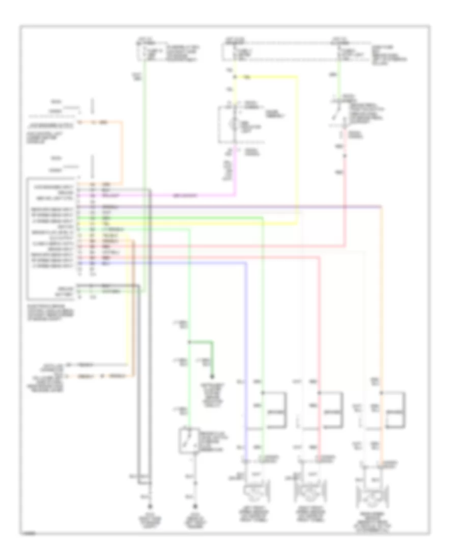
List of elements for Anti-lock Brake Wiring Diagrams for Isuzu Rodeo S 2000:
- (honda)
- (isuzu)
- (isuzu) (honda)
- 4wd control unit (under center console)
- 4wd engaged input
- 4wd engaged output
- A23
- Abs ind light ctrl
- Abs indicator light
- Battery
- Braided
- Brake fluid level in
- Brake fluid level switch (in brake fluid reservoir)
- Brake input
- Brake pedal position switch (behind dash, on brake pedal support)
- C-4
- C-5
- Class 2 serial data
- Dash fuse box (behind dash, left of steering column)
- Data link connector (dlc) (on lower left side of dash, near engine hood release lever)
- Dlc output
- Electronic brake control module (ebcm) (on right rear corner of engine compt)
- Fuse 11 meter 15a
- Fuse 18 abs 50a
- Fuse 6 stop light 15a
- Fuse/relay box (on right side of engine compartment)
- G103 (right side of engine compt)
- G104 (rear of left front fender)
- Gauge assembly
- Ground
- Honda
- Hot at all times
- Hot in on or start
- I-1
- Ignition
- Instrument cluster system (brake indicator circuit)
- Isuzu
- Left front speed sensor (on inside of front wheel)
- Lf speed sens input
- Rear spd sens input
- Rear speed sensor (beneath rear of vehicle, on top of differential)
- Red
- Rf speed sens input
- Right front speed sensor (on inside of front wheel)
 English