ANTI-LOCK BRAKES
Anti-lock Brakes Wiring Diagram for Jaguar F-Type V8 S 2014
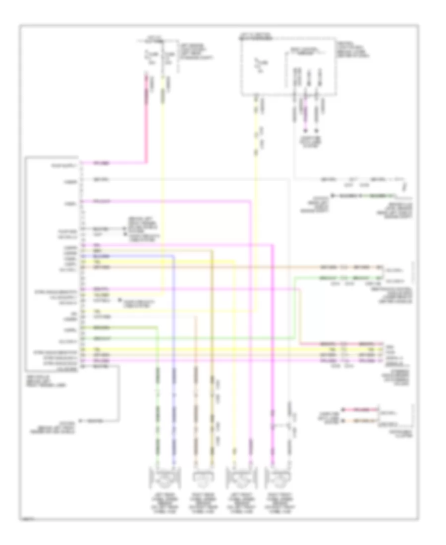
List of elements for Anti-lock Brakes Wiring Diagram for Jaguar F-Type V8 S 2014:
- (behind left front fender splash shield) g1d188b
- Abs module (behind left front fender liner)
- Body control module
- Brake fluid level sensor (rear left side of engine compt)
- C11w
- C11x
- C1bb01a
- C1bb01b
- C21a c21b
- C31a
- C31b
- C31e
- C31f
- C31g
- C31h
- C34a
- C34b
- C3bp01b
- C3bp01d
- C3bp01e
- C3r114b
- Central junction box (behind lower center of dash)
- Computer data lines system
- Fuse 30a
- Fuse 40a
- Fuse 5a
- G1d187a (rear left side of engine compt)
- G1d188a (behind left front fender splash shield)
- Gnd
- Hot at all times
- Hot w/ ignition relay energized
- Hs can hi
- Hs can lo
- Ign
- Imu can h
- Imu can l
- Instrument cluster
- Left engine junction box (left rear of engine compt)
- Left front wheel speed sensor (on left front wheel hub)
- Left rear wheel speed sensor (on left rear wheel hub)
- Level sw brk fluid
- Ms can h
- Ms can l
- Pump gnd
- Pwr
- Restraints control module (rcm) (under rear of center console)
- Right front wheel speed sensor (on right front wheel hub)
- Right rear wheel speed sensor (on right rear wheel hub)
- Signal a
- Signal b
- Steering angle sensor (on steering column)
- Strg angle sens pwr
- Strg angle sens rtn
- Strg angle sig a
- Strg angle sig b
- Valve gnd
- Wspfl
- Wspfr
- Wsprl
- Wsprr
- Wssfl
- Wssfr
- Wssrl
- Wssrr
 Русский