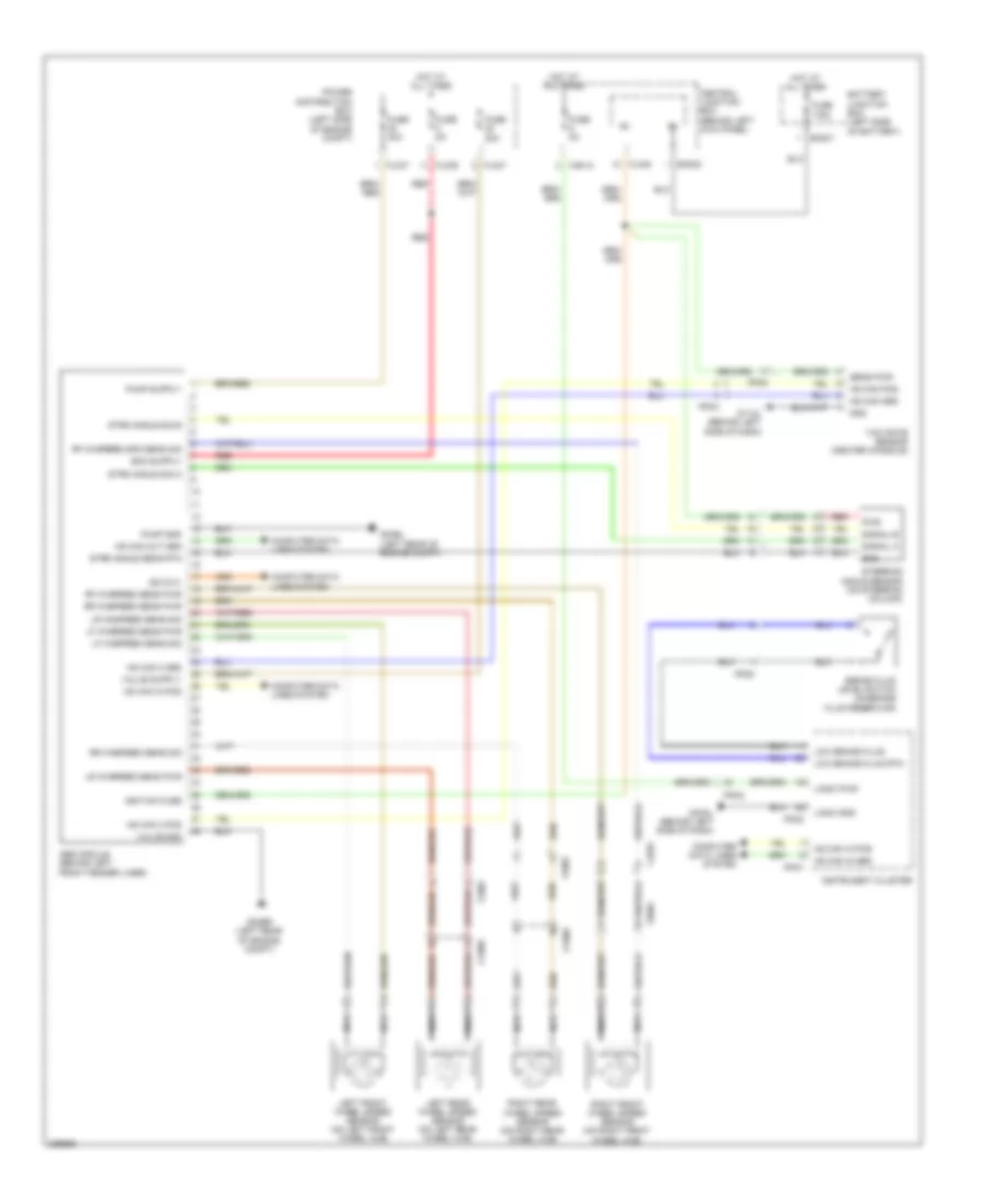
ANTI-LOCK BRAKES
Anti-lock Brakes Wiring Diagram for Jaguar XK 2012
List of elements for Anti-lock Brakes Wiring Diagram for Jaguar XK 2012:
- Abs module (behind left front fender liner)
- Ba001
- Ba002
- Battery junction box (left side of battery)
- Brake fluid level switch (on brake fluid reservoir)
- Ca015
- Central junction box (behind left kick panel)
- Computer data lines system
- Cv005
- Fl002
- Fl037
- Fl039
- Fl048
- Fl070
- Fr001
- Fuse 175a
- Fuse 20a
- Fuse 40a
- Fuse 5a
- G03bl (left rear of engine compt)
- G03br (left rear of engine compt)
- G11al (behind left side of dash)
- G40al (behind left side of dash)
- Gnd
- Hot at all times
- Hs can 2 pos
- Hs can in pos
- Hs can pos
- Ignition fuse
- Instrument cluster
- Ip002
- Ip004
- Ip031
- Ip032
- Ip054
- Iso 9141
- Left front wheel speed sensor (on left front wheel hub)
- Left rear wheel speed sensor (on left rear wheel hub)
- Lf whspeed sens pwr
- Lf whspeed sens sig
- Logic gnd
- Logic pwr
- Low brake fluid
- Low brake fluid rtn
- Lr whspeed sens pwr
- Lr whspeed sens sig
- Nca
- Power distribution box (left side of engine compt)
- Pump gnd
- Pwr
- Red
- Rf whspeed sens pwr
- Rf whspeed spd sens sig
- Right front wheel speed sensor (on right front wheel hub)
- Right rear wheel speed sensor (on right rear wheel hub)
- Rr whspeed sens pwr
- Rr whspeed sens sig
- Sens pwr
- Signal a
- Signal b
- Steering angle sensor (on steering column)
- Strg angle sens rtn
- Strg angle sig a
- Strg angle sig b
- Valve gnd
- Yaw rate sensor (center console)
 Русский