ANTI-LOCK BRAKES
Anti-lock Brakes Wiring Diagram for Jaguar XKR 2000
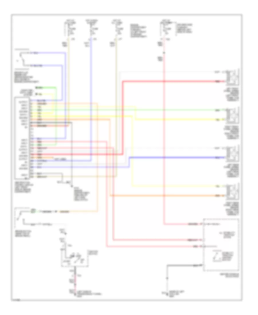
List of elements for Anti-lock Brakes Wiring Diagram for Jaguar XKR 2000:
- (base of left a-pillar) g900
- (i) acc
- (ii) run
- (left side of transmission tunnel) g302
- (not used)
- Abs/traction control module (left front side of engine compartment)
- Brake fluid reservoir (brake booster enclosure in engine compartment)
- Brake switch (near top of brake pedal)
- Center console swich pack
- Computer data lines system
- Data +
- Data -
- Driver's side fuse box (behind left side of dash)
- Engine compartment fuse box (in left front of engine compartment)
- Fc4
- Fc5
- Fuse 30a
- Fuse 5a
- G104 (engine compartment, forward of left hand hood catch)
- Hot at all times
- Hot in run & start
- Ignition switch
- Input
- Left front wheel speed sensor (left front wheel hub assembly)
- Left rear wheel speed sensor (left rear wheel hub assembly)
- Lf5
- Lf7
- Lf8
- Nca
- Off (0)
- Output
- Red
- Right front wheel speed sensor (right front wheel hub assembly)
- Right rear wheel speed sensor (right rear wheel hub assembly)
- Sig gnd
- Stability/ traction control switch
- Stability/ traction state
- Start (iii)
 English