ANTI-LOCK BRAKES
Anti-lock Brake Wiring Diagrams for Jeep Cherokee Sport 1995
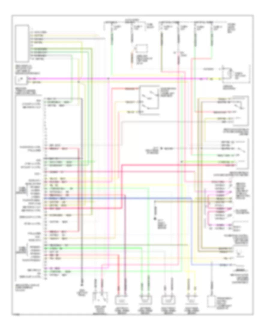
List of elements for Anti-lock Brake Wiring Diagrams for Jeep Cherokee Sport 1995:
- A/t only
- Abs control module (near steering column)
- Abs data link con- nector (center of i/p, below abs control module)
- Abs diode (taped in harness near controller)
- Abs hydraulic actuation unit (left rear of engine compartment)
- Abs power relay (in power distribution center)
- Abs pump motor (left rear of engine compartment)
- Abs pump motor relay (in power distribution center)
- Abs pwr rly ctrl
- Abs pwr rly out
- Abs warn lp
- Accel sw 1
- Accel sw 2
- Accel sw gnd
- Acceleration switch (under left rear seat)
- B/h conn
- B116
- B205
- B207
- B210
- B219
- B220
- B234
- B235
- B236
- B245
- B248
- B249
- B251
- B254
- B515
- B516
- B517
- Bulkhead connector
- Bus (+)
- Bus (-)
- Ccd +
- Ccd -
- Check anti-lock ind
- Fuse 10 30a
- Fuse 13 15a
- Fuse 17 7.5a
- Fuse 4 20a
- Fuse 7 2a
- Fuse 8 40a
- Fuse block
- G117 (right rear of engine)
- G200 (left kick panel)
- Gnd
- Headlamp delay module (left side of i/p)
- Hot at all times
- Hot in run
- Hot in start and run
- Ign
- L50
- Left front wheel speed sensor
- Left rear wheel speed sensor
- Lf dump vlv ctrl
- Lf iso vlv ctrl
- Lf sens +
- Lf sens -
- Lr sens +
- Lr sens -
- Pnk
- Power distri- bution box
- Powertrain control module (pcm) (left fender side shield)
- Pts jumper
- Pump/mtr rly ctrl
- Pump/mtr sens +
- Pump/mtr sens -
- Rear dump vlv ctrl
- Rear inlet vlv ctrl
- Red
- Rf dump vlv ctrl
- Rf iso vlv ctrl
- Rf sens +
- Rf sens -
- Right front wheel speed sensor
- Right rear wheel speed sensor
- Rr sens +
- Rr sens -
- Sensor
- Stop lamp switch (top of brake pedal)
- Stop lp sig
- Tan
- Transmission control module (lower right side of i/p)
- Warning indicators
- Wheel speed sensors
 English