ANTI-LOCK BRAKES
Anti-lock Brake Wiring Diagrams for Jeep Cherokee Sport 1997
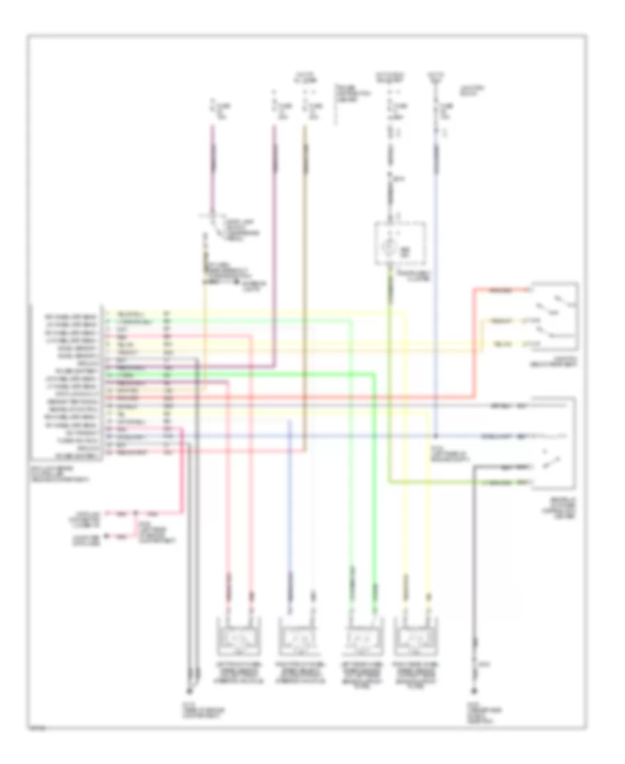
List of elements for Anti-lock Brake Wiring Diagrams for Jeep Cherokee Sport 1997:
- (i/p harn, near breakout to brake switch) s203
- A10
- A20
- Abs ind.
- Abs relay (in power distribution center)
- Abs relay control
- Accel sensor 1
- Accel sensor 2
- Anti-lock brake controller (engine compartment)
- B16
- B18
- B19
- B20
- B41
- B42
- B43
- Computer data lines
- D21
- Data link connector (lower i/p)
- Exterior lights
- F15
- Fuse 10a
- Fuse 15a
- Fuse 20a
- Fuse 40a
- Fused ign (run)
- G switch (below rear seat)
- G100 (fender side shield, near pcm)
- G115 (rear of engine compartment)
- G83
- Ground
- Hot at all times
- Hot in run
- Hot in run and start
- Instrument cluster
- Junction block
- L50
- Left front wheel speed sensor (on left front steering knuckle)
- Left rear wheel speed sensor (on left rear brake support plate)
- Lf wheel spd sens +
- Lf wheel spd sens -
- Lr wheel spd sens +
- Lr wheel spd sens -
- Pnk
- Power (battery)
- Power distribution center
- Red
- Rf wheel spd sens +
- Rf wheel spd sens -
- Right front wheel speed sensor (on right front steering knuckle)
- Right rear wheel speed sensor (on right rear brake support plate)
- Rr wheel spd sens +
- Rr wheel spd sens -
- S13
- S132
- S134 (left rear of engine compt.)
- S139 (left rear of engine compartment)
- S216
- Sci transmit
- Sensor test signal
- Stop lamp switch (near brake pedal)
- Stop lmp sw out
 English