ANTI-LOCK BRAKES
Anti-lock Brakes Wiring Diagram for Jeep Liberty Renegade 2004
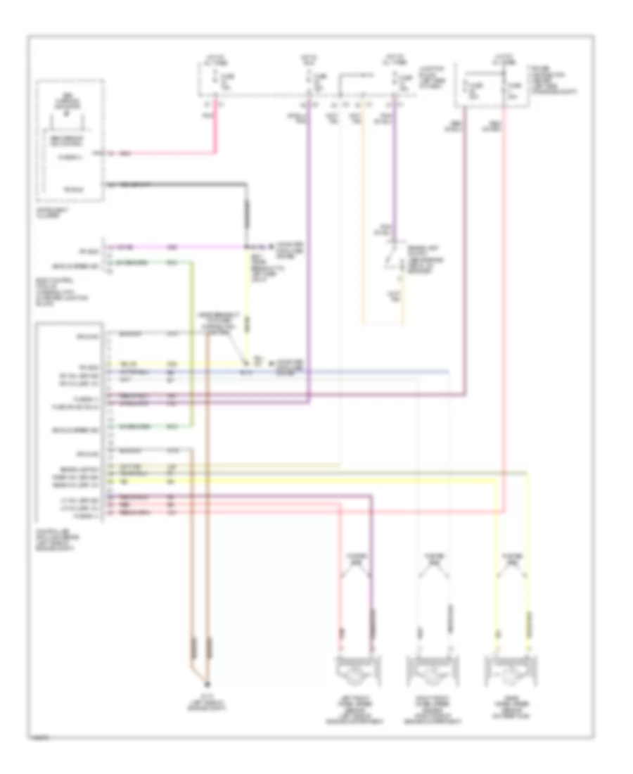
List of elements for Anti-lock Brakes Wiring Diagram for Jeep Liberty Renegade 2004:
- (near breakout to power distribution center)
- A10
- A20
- Abs warning ind control
- Abs warning indicator
- B12
- Body control module (integral with outboard junction block)
- Brake lamp sw
- Brake lamp switch (above brake pedal, on bracket)
- Computer data lines system
- Controller anti-lock brake (left side of engine compt)
- D25
- F22
- Fuse 10a
- Fuse 15a
- Fuse 20a
- Fuse 40a
- Fuse b (+)
- Fuse ign sw (run)
- G110 (left side of engine compt)
- Ground
- Hot at all times
- Hot in run
- Instrument cluster
- Junction block (left side of dash)
- L50
- Left front wheel speed sensor (left side of engine compartment)
- Lf whl spd 12v
- Lf whl spd sig
- Pci bus
- Pnk
- Power distribution center (left side of engine compt)
- Rear wheel speed sensor (on rear axle)
- Rear whl spd 12v
- Rear whl spd sig
- Red
- Rf whl spd 12v
- Rf whl spd sig
- Right front wheel speed sensor (right side of engine compartment)
- S112
- S201 (near breakout to left dash light)
- Twisted pair
- Vehicle speed sig
- Z101
- Z102
 Deutsch