ANTI-LOCK BRAKES
Anti Lock Brake Wiring Diagram for Land Rover Discovery 3 SE 2006

List of elements for Anti Lock Brake Wiring Diagram for Land Rover Discovery 3 SE 2006:
- (right front wheel arch liner) c2603
- Abs ind
- Abs module (left rear of engine compt)
- Afs ecu
- Air suspension control module (base of left "a" pillar)
- Battery junction box
- Bla
- Bls
- C0040
- C0582 red
- C0867l
- C2114
- C2627 (right "a" pillar)
- Can m
- Can p
- Can-h
- Can-l
- Center console switch pack
- Center facia switch pack
- Central junction box
- Computer data lines system
- Diagnostic socket (under left side of dash)
- Dpfl
- Dpfr
- Dprl
- Dprr
- Drsr
- Drss
- Drst
- Dsfl
- Dsfr
- Dsrl
- Dsrr
- Exterior lights system
- Fuse 15a
- Fuse 25a
- Fuse 5a
- Fuse link 9 40a
- Gnd
- Hdc sw
- Hill descent relay
- Hot at all times
- Hot in run
- Ign
- Instrument cluster
- K-line
- Left front wheel speed sensor (left front wheelwell)
- Left rear wheel speed sensor (below left rear wheelwell)
- M gnd
- Mdo-2
- Navigation system module
- Nca
- Red
- Reset
- Right front wheel speed sensor (right front wheelwell)
- Right rear wheel speed sensor (below right rear wheelwell)
- Sgnd
- Sin 1
- Sot 1
- Speed control module
- Steering angle sensor (on underside of steering column)
- Stop lamp switch
- Tcsaus
- Ubmr
- Ubvr
- Vso
- Yaw rate sensor (under center console)
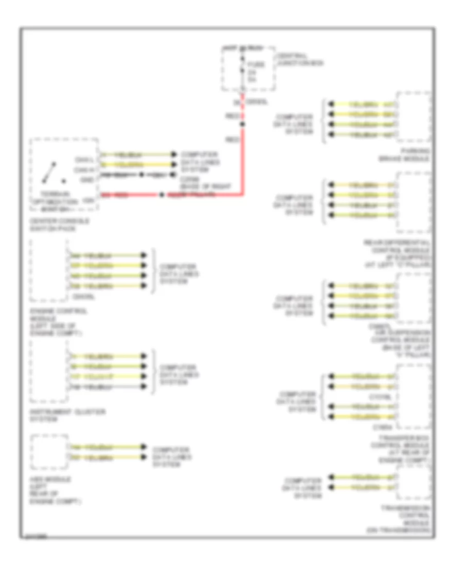
Terrain Response Wiring Diagram for Land Rover Discovery 3 SE 2006
List of elements for Terrain Response Wiring Diagram for Land Rover Discovery 3 SE 2006:
- Abs module (left rear of engine compt)
- Air suspension control module (base of left "a" pillar)
- C0583l
- C0635l
- C0867l
- C1319l
- C1854
- C2598 (base of right "b" pillar)
- Can h
- Can l
- Center console switch pack
- Central junction box
- Computer data lines system
- Engine control module (left side of engine compt)
- Fuse 5a
- Gnd
- Hot in run
- Ign
- Instrument cluster system
- Parking brake module
- Rear differential control module (if equipped) (at left "c" pillar)
- Red
- Terrain optimization switch
- Transfer box control module (at rear of engine compt)
- Transmission control module (on transmission)