ANTI-LOCK BRAKES
Anti Lock Brake Wiring Diagram for Land Rover Range Rover Sport Supercharged 2008

List of elements for Anti Lock Brake Wiring Diagram for Land Rover Range Rover Sport Supercharged 2008:
- (behind left front wheelwell)
- Abs module (right rear of engine compt)
- Afs control module (behind top of left kick panel)
- Air suspension control module (behind left kick panel)
- Bla
- Bls
- C0040
- C0582 red
- C2114
- C2603
- C2627 (behind left kick panel)
- C3196 (under center console)
- Can h
- Can l
- Can-h
- Can-l
- Center console switch pack
- Center fascia switch pack
- Central junction box (behind right side of dash)
- Computer data lines system
- Diagnostic socket (under left side of dash)
- Dpfl
- Dpfr
- Dprl
- Dprr
- Dsfl
- Dsfr
- Dsrl
- Dsrr
- Dynamic response module (behind left kick panel)
- Engine junction box (under engine compartment fuse box)
- Exterior lights system
- Fuse 15a
- Fuse 25a
- Fuse 5a
- Fuse link 9 40a
- Gnd
- Hdc sw
- Hill descent relay
- Hot at all times
- Hot in run
- Hs can h
- Hs can l
- Ign
- Instrument cluster
- K-line
- Left front wheel speed sensor (at left front wheel hub assembly)
- Left rear wheel speed sensor (at left rear wheel hub assembly)
- M gnd
- Navigation system module (under driver's seat)
- Nca
- Red
- Right front wheel speed sensor (at right front wheel hub assembly)
- Right rear wheel speed sensor (at right rear wheel hub assembly)
- Speed control module (behind left kick panel)
- Steering angle sensor (on underside of steering column)
- Stoplight switch (under left side of dash)
- Tcsaus
- Ubmr
- Ubvr
- Vso
- Yaw rate sensor (under center console)
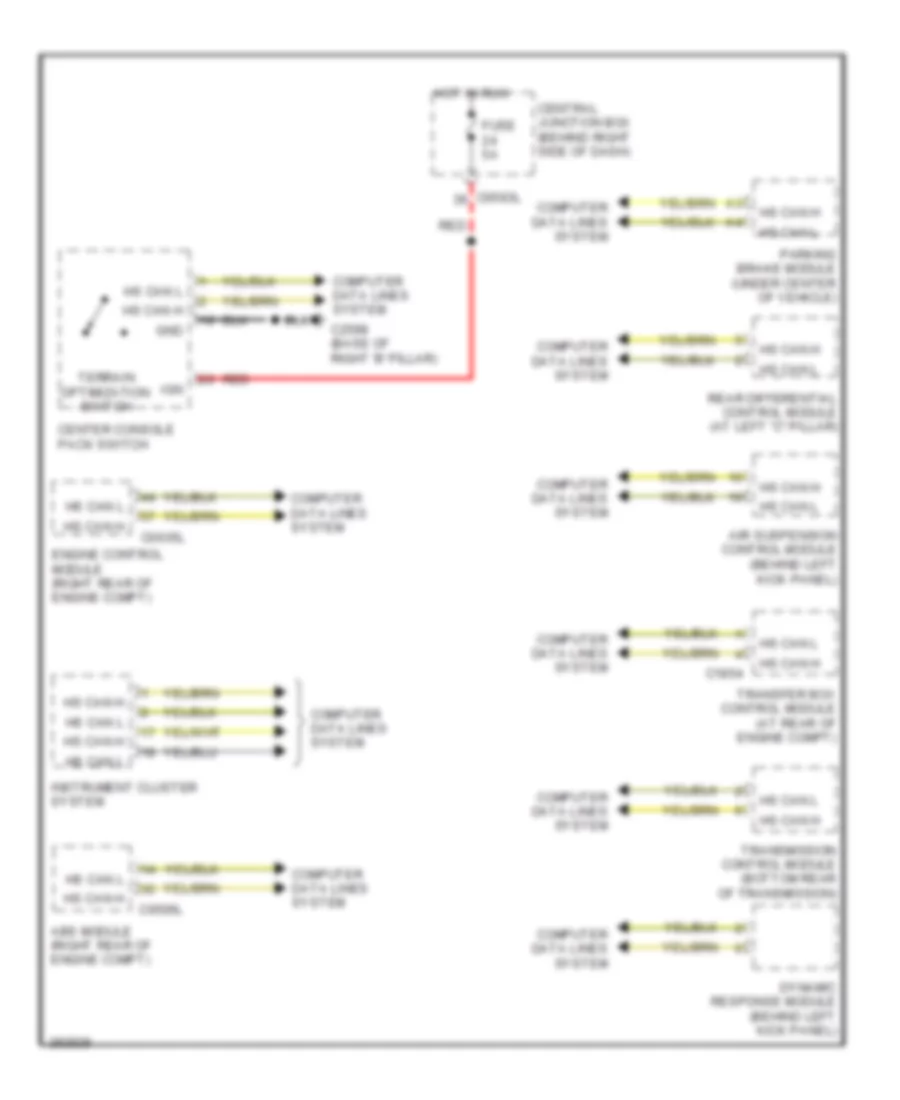
Terrain Response Wiring Diagram for Land Rover Range Rover Sport Supercharged 2008
List of elements for Terrain Response Wiring Diagram for Land Rover Range Rover Sport Supercharged 2008:
- Abs module (right rear of engine compt)
- Air suspension control module (behind left kick panel)
- C0506l
- C0583l
- C0635l
- C1854
- C2598 (base of right 'b' pillar)
- Center console pack switch
- Central junction box (behind right side of dash)
- Computer data lines system
- Dynamic response module (behind left kick panel)
- Engine control module (right rear of engine compt)
- Fuse 5a
- Gnd
- Hot in run
- Hs can h
- Hs can l
- Ign
- Instrument cluster system
- Parking brake module (under center of vehicle)
- Rear differential control module (at left "c" pillar)
- Red
- Terrain optimization switch
- Transfer box control module (at rear of engine compt)
- Transmission control module (bottom rear of transmission)