ANTI-LOCK BRAKES
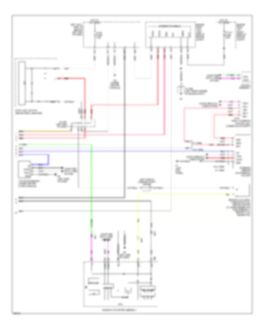
Anti-lock Brakes Wiring Diagram (1 of 2) for Lexus GS 350 2013

List of elements for Anti-lock Brakes Wiring Diagram (1 of 2) for Lexus GS 350 2013:
Anti-lock Brakes Wiring Diagram (2 of 2) for Lexus GS 350 2013
List of elements for Anti-lock Brakes Wiring Diagram (2 of 2) for Lexus GS 350 2013: