ANTI-LOCK BRAKES
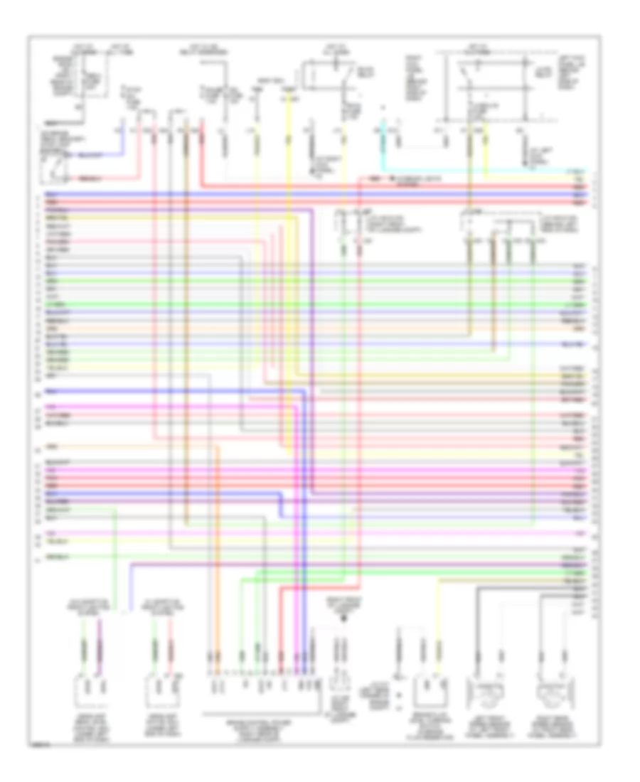
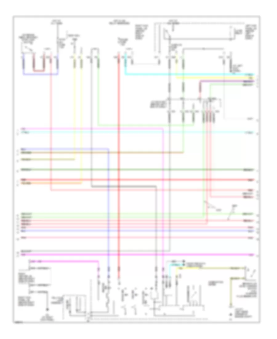
Anti-lock Brakes Wiring Diagram, with Vehicle Dynamics Integrated Management (1 of 4) for Lexus GS 430 2007

List of elements for Anti-lock Brakes Wiring Diagram, with Vehicle Dynamics Integrated Management (1 of 4) for Lexus GS 430 2007:
- (left rear corner of engine compt) a2
- A1 (left rear corner of engine compt)
- A13
- A14
- A41
- A42
- Abs main1 fuse 10a
- Abs main1 relay
- Abs main2 fuse 10a
- Abs main2 relay
- Abs main3 fuse 10a
- Abs motor fuse 30a
- Abs mtr1 relay
- Abs mtr2 relay
- Brake pedal stroke sensor (top of brake pedal assembly)
- Brake stroke simulator cylinder (left rear of engine compt)
- Bs01
- Bs03
- Bs1
- Bsr
- Cbi1
- Computer data lines system
- Cty+
- Di1
- Do1
- Dome fuse 10a
- Ena
- Engine room r/b 1 (right rear of engine compt)
- Engine room r/b 3 (left rear of engine compt)
- Fail
- Fr+
- Fr-
- Fra+
- Fra-
- Fro
- Frr+
- Frr-
- Gnd
- Hot at all times
- Ig1
- J/c a32 (behind left end of dash)
- Left rear speed sensor (at left rear wheel assembly)
- Mpx-b fuse 10a
- Mr1
- Mtt
- Pac1
- Parking brake switch (behind left side of dash)
- Pck1
- Pfr
- Pmc1
- Pnk
- Prl
- R1+
- R1-
- R3+
- Red
- Right front speed sensor (at right front wheel assembly)
- Rl+
- Rl-
- Rla+
- Rla-
- Rlr+
- Rlr-
- Scss
- Short connector a41 & a42 (brake stroke simulator cylinder)
- Skg
- Skid control ecu (left rear of engine compt)
- Sks
- Sks1
- Sks2
- Smc1
- Sp1
- Stp
- Vbz
- Vcm
- Vcsk
- Vsc warning buzzer (behind left side of dash)
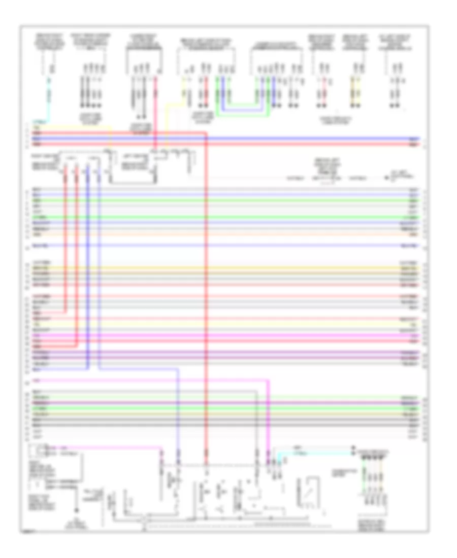
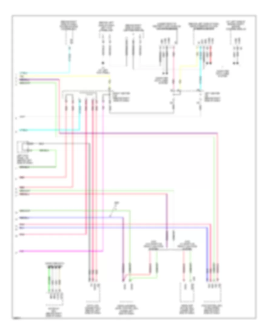
Anti-lock Brakes Wiring Diagram, with Vehicle Dynamics Integrated Management (2 of 4) for Lexus GS 430 2007
List of elements for Anti-lock Brakes Wiring Diagram, with Vehicle Dynamics Integrated Management (2 of 4) for Lexus GS 430 2007:
- (at left kick panel) k1
- (at right kick panel) k4
- (on brake pedal bracket) stop lamp switch
- (right front of luggage compt) u2
- +bc
- A24
- A25
- A28 spdl
- A33
- Abs 2 fuse 30a
- Body ecu
- Brake fluid level warning switch (in brake fluid reservoir)
- Cty
- Cty+
- D11
- D12
- D23
- D29
- Ena
- Engine room j/b 1 (right rear of engine compt)
- Fail
- Gauge fuse 7.5a
- Gnd
- Headlamp beam level control ecu (under left end of dash)
- Headlamp swivel ecu (under left end of dash)
- Hot at all times
- Hot w/ ig2 relay energized
- Ig1
- Ign fuse 10a
- Interior lights system
- J/c a17 (left rear corner of engine compt)
- J/c a32 & a33 (behind left end of dash)
- J/c u22 & u23 (right front of luggage compt)
- J/c u25 (right front of luggage compt)
- J13
- K67
- L10
- Lbl
- Left front speed sensor (at left front wheel assembly)
- Left kick panel j/b (behind left side of dash)
- Lh-ecu-ig fuse 10a
- Lh-ig2 relay
- Out1
- Out2
- Pkb
- Pkbo
- Pnk
- Red
- Rh-ig fuse 7.5a
- Rh-ig1 relay
- Right kick panel j/b (behind right side of dash)
- Right rear speed sensor (at right rear wheel assembly)
- Spdl
- Spdr
- Stop sw fuse 7.5a
- U22
- U23
- W/ adaptive front-lighting system
- W/o adaptive front-lighting system
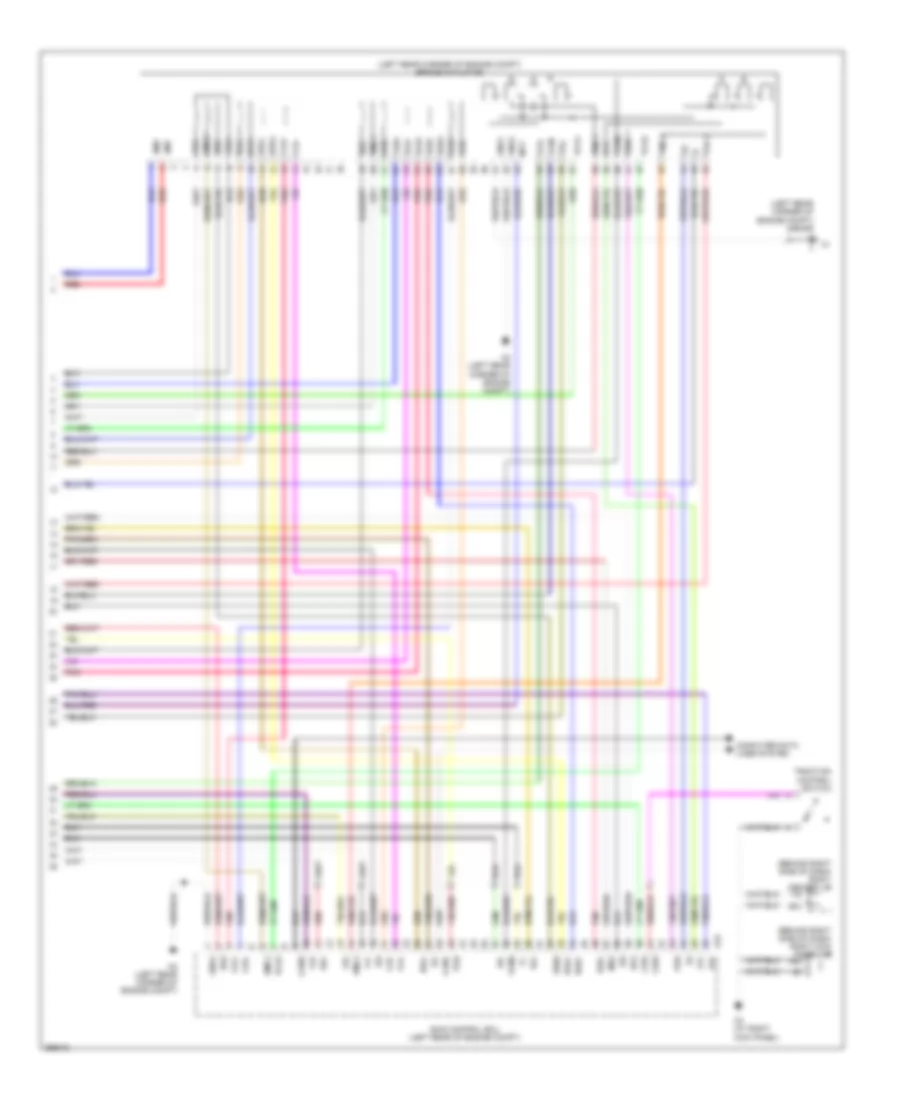
Anti-lock Brakes Wiring Diagram, with Vehicle Dynamics Integrated Management (3 of 4) for Lexus GS 430 2007
List of elements for Anti-lock Brakes Wiring Diagram, with Vehicle Dynamics Integrated Management (3 of 4) for Lexus GS 430 2007:
- (at left kick panel) k1
- (at left side of engine compt) engine control module
- (behind left side of dash) distance control ecu
- (behind left side of dash) left kick panel j/b
- (behind left side of dash, near steering column) steering sensor
- (behind right end of dash) absorber control ecu
- (behind right side of dash) power source control ecu
- (right rear corner of engine compt) power steering ecu
- (under front of center floor console) yaw rate sensor
- (under glove compt) steering control ecu
- +bo
- A40
- Abs ind
- Bat
- Brake ind
- C15
- Ca1h
- Ca1l
- Can+
- Can-
- Canh
- Canl
- Combination meter
- Computer data lines system
- D11
- Ecb or vsc ind
- Ess
- G11
- Gateway ecu (behind right side of dash)
- Grd
- I14
- Ig+
- Ig1d
- Ind master
- J15
- K31
- K4 (at right kick panel)
- K70
- K72
- Left center j/b (behind right side of dash)
- Mpi1
- Mpi2
- Mpx+
- Mpx-
- Pnk
- Red
- Right center j/b (behind right side of dash)
- Right kick panel j/b (behind right side of dash)
- Slip ind
- Speedometer
- Ss1+
- Ss1-
- Telltale lamp assembly
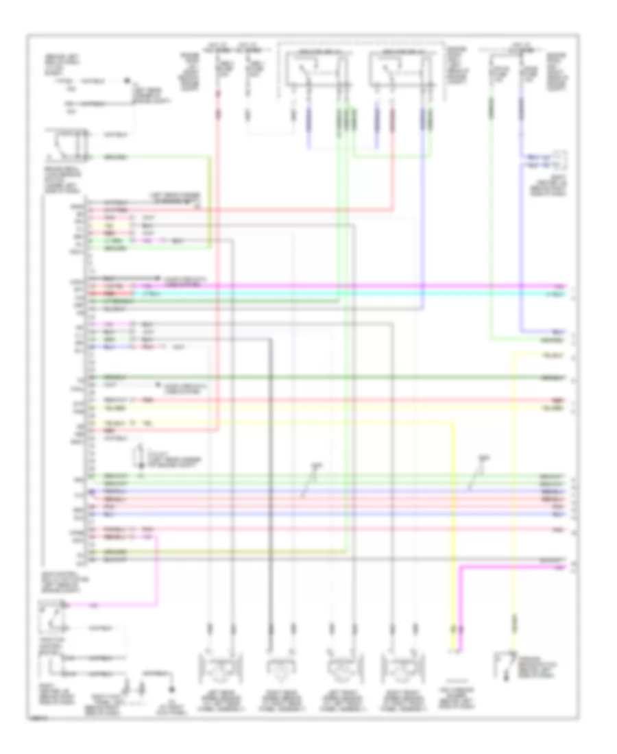
Anti-lock Brakes Wiring Diagram, with Vehicle Dynamics Integrated Management (4 of 4) for Lexus GS 430 2007
List of elements for Anti-lock Brakes Wiring Diagram, with Vehicle Dynamics Integrated Management (4 of 4) for Lexus GS 430 2007:
- (behind right side of dash) right center j/b
- (behind right side of dash) right kick panel j/b
- (left rear corner of engine compt) brake actuator
- (left rear corner of engine compt) j/c a17
- A10
- A15
- A2 (left rear corner of engine compt)
- Bm1
- Bm2
- Bs02
- Bs1
- Bs2
- Canh
- Canl
- Cbi2
- Computer data lines system
- Csw
- Di2
- Do2
- E13
- Fl+
- Fl-
- Fla+
- Fla-
- Flo
- Flr+
- Flr-
- Fra+
- Fra-
- Frr+
- Frr-
- Gnd1
- Gnd2
- Gnd4
- I15
- Ig2
- K4 (at right kick panel)
- Lbl
- Mr2
- Mtt
- Pac1
- Pck1
- Pck2
- Pfl
- Pfr
- Pkb
- Pmc1
- Pmc2
- Pnk
- Prl
- Prr
- R2+
- R2-
- R4+
- Red
- Rla+
- Rla-
- Rlr+
- Rlr-
- Rr+
- Rr-
- Rra+
- Rra-
- Rrr+
- Rrr-
- Skid control ecu (left rear of engine compt)
- Smc1
- Smc2
- Traction control switch
- Vcm
- Vcm2
Anti-lock Brakes Wiring Diagram, without Vehicle Dynamics Integrated Management (1 of 3) for Lexus GS 430 2007
List of elements for Anti-lock Brakes Wiring Diagram, without Vehicle Dynamics Integrated Management (1 of 3) for Lexus GS 430 2007:
- (behind left end of dash) j/c a32 & a33
- (left rear corner of engine compt) a2
- +bs
- 2wd
- 4wd
- A1 (left rear corner of engine compt)
- A32
- A33
- Abs 1 fuse 50a
- Abs 2 fuse 30a
- Abs mtr1 relay
- Abs mtr2 relay
- Brake pedal load sensing switch (under left side of dash)
- C15
- Canh
- Canl
- Computer data lines system
- Csw
- D/g
- D11
- Dome fuse 10a
- Engine room j/b 1 (right rear of engine compt)
- Engine room r/b 1 (right rear of engine compt)
- Engine room r/b 3 (left rear of engine compt)
- Fl+
- Fl-
- Flo
- Fr+
- Fr-
- Fro
- Fsw+
- Gnd1
- Gnd2
- Hot at all times
- I15
- Ig1
- J/c a17 (left rear corner of engine compt)
- K4 (at right kick panel)
- Left front speed sensor (at left front wheel assembly)
- Left rear speed sensor (at left rear wheel assembly)
- Mpx-b fuse 10a
- Mrf
- Parking brake switch (behind left side of dash)
- Pkb
- Pnk
- Red
- Right center j/b (behind right side of dash)
- Right front speed sensor (at right front wheel assembly)
- Right kick panel j/b (behind right side of dash)
- Right rear speed sensor (at right rear wheel assembly)
- Rl+
- Rl-
- Rlo
- Rr+
- Rr-
- Rro
- Skid control ecu w/ actuator (left rear of engine compt)
- Sp1
- Stp
- Traction control switch
- Vsc warning buzzer (behind left side of dash)
- Wfse
Anti-lock Brakes Wiring Diagram, without Vehicle Dynamics Integrated Management (2 of 3) for Lexus GS 430 2007
List of elements for Anti-lock Brakes Wiring Diagram, without Vehicle Dynamics Integrated Management (2 of 3) for Lexus GS 430 2007:
- (at left kick panel) k1
- (on brake pedal bracket) stop lamp switch
- 2wd
- 4wd
- A24
- A25
- A33
- Abs ind
- Body ecu
- Brake fluid level warning switch (3.5l) (in brake fluid reservoir)
- Brake ind
- C15
- Combination meter
- Computer data lines system
- D11
- D12
- D18
- D23
- D29
- Ecb or vsc ind
- Gauge fuse 7.5a
- Hot at all times
- Hot w/ ig2 relay energized
- Ig+
- J/c a17 (left rear corner of engine compt)
- J/c a32 & a33 (behind left end of dash)
- J15
- K31
- K4 (at right kick panel)
- L10
- Left kick panel j/b (behind left side of dash)
- Lh-ecu-ig fuse 10a
- Lh-ig2 relay
- Master ind
- Mpx+
- Mpx-
- Pkb
- Pnk
- Red
- Right center j/b (behind right side of dash)
- Right kick panel j/b (behind right side of dash)
- Slip ind
- Speedometer
- Stop sw fuse 7.5a
- Telltale lamp assembly
Anti-lock Brakes Wiring Diagram, without Vehicle Dynamics Integrated Management (3 of 3) for Lexus GS 430 2007
List of elements for Anti-lock Brakes Wiring Diagram, without Vehicle Dynamics Integrated Management (3 of 3) for Lexus GS 430 2007:
- (at left side of engine compt) engine control module
- (behind left side of dash) left kick panel j/b
- (behind left side of dash, near steering column) steering sensor
- (behind right side of dash) left center j/b
- (behind right side of dash) power source control ecu
- (under front of center floor console) yaw rate sensor
- 2wd
- 4wd control ecu (if equipped) (behind right side of dash)
- 4wd w/ adaptive front-lightning system
- 4wd w/o adaptive front-lightning system
- A28
- Bat
- C13
- Ca1h
- Ca1l
- Canh
- Canl
- Computer data lines system
- D13
- D15
- D30
- Data link connector 3 (behind left side of dash)
- Ess
- Flo
- Fro
- Gateway ecu (behind right side of dash)
- Gnd
- Headlamp beam level control ecu (under left end of dash)
- Headlamp swivel ecu (under left end of dash)
- I14
- Ig1d
- J15
- K1 (at left kick panel)
- Left center j/b (behind right side of dash)
- Left kick panel j/b (behind left side of dash)
- Mpi1
- Mpi2
- Pnk
- Red
- Right center j/b (behind right side of dash)
- Rlo
- Rro
- Sil
- Spdl
- Spdr
- Wfse