ANTI-LOCK BRAKES
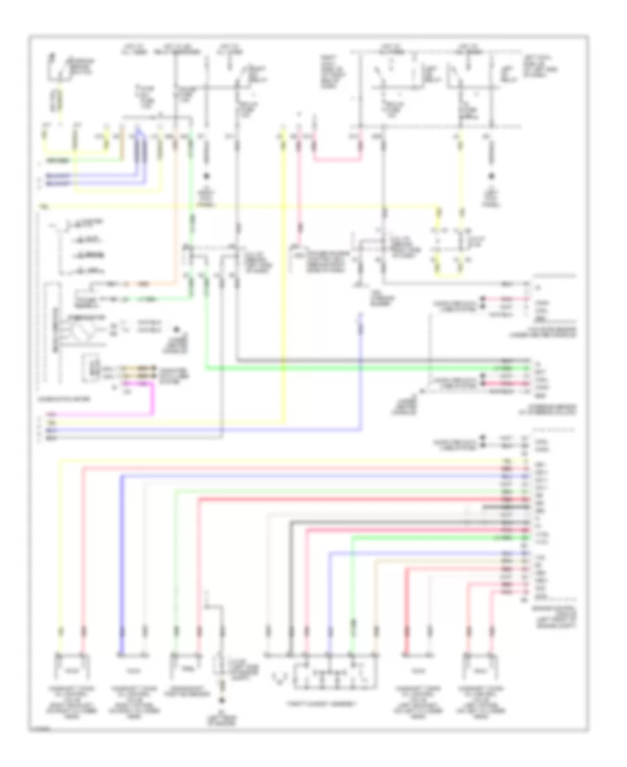
Anti-lock Brakes Wiring Diagram, with Vehicle Dynamics Integrated Management (1 of 2) for Lexus IS 350 2006

List of elements for Anti-lock Brakes Wiring Diagram, with Vehicle Dynamics Integrated Management (1 of 2) for Lexus IS 350 2006:
- (a/t)
- (left rear of engine compt) a3
- +bs
- 4wd control ecu (right kick panel)
- A/t
- A1 (left rear of engine compt)
- A2 (left rear of engine compt)
- A33
- Abs 1 fuse 50a
- Abs 2 fuse 30a
- Abs mtr1 relay
- Abs mtr2 relay
- Brake lamp relay
- Brake pedal road sensing switch
- Canh
- Canl
- Computer data lines system
- Csw
- D/g
- Data link connector 3 (behind lower left side of dash)
- Engine room 1 r/b (on right rear of engine compt)
- Engine room 2 r/b (left side of engine compt)
- Engine room 3 r/b (left rear of engine compt)
- Fl+
- Fl-
- Flo
- Fr+
- Fr-
- Fro
- Fsw+
- Grd1
- Grd2
- Headlamp swivel ecu (left kick panel)
- Hot at all times
- Ig1
- J/c a29 (at left kick panel)
- J/c a33 & j80 (at right kick panel)
- J2 (under center console)
- J80
- Left front speed sensor
- Left rear speed sensor
- M/t
- Mpx-b fuse 10a
- Mpx1
- Mpx2
- Mrf
- Pkb
- Pnk
- Red
- Right front speed sensor
- Right rear speed sensor
- Rl+
- Rl-
- Rlo
- Rr+
- Rr-
- Rro
- Sil
- Skid control ecu w/ actuator (left rear of engine compt)
- Sp1
- Spdl
- Spdr
- Stop lamp switch
- Stp1
- Stp2
- Stpo
- Traction control switch
- Wfse
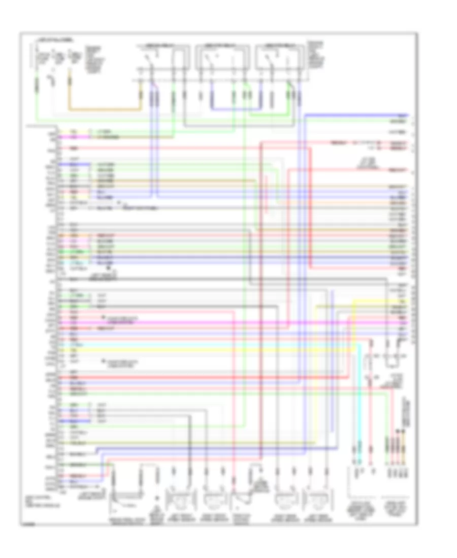
Anti-lock Brakes Wiring Diagram, with Vehicle Dynamics Integrated Management (2 of 2) for Lexus IS 350 2006
List of elements for Anti-lock Brakes Wiring Diagram, with Vehicle Dynamics Integrated Management (2 of 2) for Lexus IS 350 2006:
- A/t
- A12
- A24
- A25
- Abs
- Bat
- Brake
- Camshaft timing oil control valve (left exhaust) (on left cylinder head)
- Camshaft timing oil control valve (left intake) (on left cylinder head)
- Camshaft timing oil control valve (right exhaust) (on right cylinder head)
- Camshaft timing oil control valve (right intake) (on right cylinder head)
- Canh
- Canl
- Combination meter
- Computer data lines system
- Crankshaft position sensor
- D11
- D12
- D13
- D29
- E1 (left rear of engine)
- Ecu-ig fuse 10a
- Engine control module (left front of engine compt)
- Ess
- Gauge fuse 7.5a
- Ge0
- Grd
- Hot at all times
- Hot w/ ig2 relay energized
- Ig fuse 10a
- Ig+
- Ig1d
- Input circuit
- J/c a7 & a8
- J/c e1 (left side of engine compt)
- J/c j27 (behind left side of dash)
- J/c j70 (behind right side of dash)
- J1 (left kick panel)
- J2 (under center console)
- J34
- J4 (right kick panel)
- L10
- Left cowl side j/b (at left end of dash)
- Left ig1 relay
- Left ig2 relay
- M/t
- Master
- Micro computer
- Mpx+
- Mpx-
- Nca
- Ne+
- Ne-
- Oc1+
- Oc2+
- Oc2-
- Oe1+
- Oe1-
- Oe2+
- Oe2-
- Parking brake switch
- Pnk
- Power source control ecu (behind right side of dash)
- Red
- Right cowl side j/b (at right end of dash)
- Right ig1 relay
- Slip
- Speedometer
- Steering sensor (at steering column)
- Stop sw fuse 7.5a
- Throttle body assembly
- Vc2
- Vsc warning buzzer
- Vta1
- Vta2
- Yaw rate sensor (under center console)
Anti-lock Brakes Wiring Diagram, without Vehicle Dynamics Integrated Management (1 of 3) for Lexus IS 350 2006
List of elements for Anti-lock Brakes Wiring Diagram, without Vehicle Dynamics Integrated Management (1 of 3) for Lexus IS 350 2006:
- A1 (left rear of engine compt)
- A2 (left rear of engine compt)
- A3 (left rear of engine compt)
- A33
- A35
- Abs 1 fuse 50a
- Abs 3 fuse 25a
- Abs mtr1 relay
- Abs mtr2 relay
- Abs sol relay
- Ast
- Brake pedal road sensing switch
- Canh
- Canl
- Computer data lines system
- Csw
- D/g
- Data link connector 3 (behind lower left side of dash)
- Engine room 1 r/b (on right rear of engine compt)
- Engine room 3 r/b (left rear of engine compt)
- Fl+
- Fl-
- Fla+
- Fla-
- Flo
- Fr+
- Fr-
- Fra+
- Fra-
- Fro
- Fss
- Fsw+
- Grd1
- Grd2
- Grd3
- Headlamp swivel ecu (left kick panel)
- Hot at all times
- Ig1
- J/c a29 (at left kick panel)
- J/c a33 & j80 (at right kick panel)
- J2 (under center console)
- J4 (right kick panel)
- J77
- J78
- J80
- Left front speed sensor
- Left rear speed sensor
- Lines system computer data
- Mpx-b fuse 10a
- Mpx1
- Mpx2
- Mrf
- Nca
- Pkb
- Pmc
- Pnk
- Red
- Right front speed sensor
- Right rear speed sensor
- Rl+
- Rl-
- Rla+
- Rla-
- Rr+
- Rr-
- Rra+
- Rra-
- Sel2
- Sflr
- Sfrr
- Sil
- Skid control ecu (center console)
- Sm1+
- Sm1-
- Sm2+
- Sm2-
- Sp1
- Spdl
- Spdr
- Srlr
- Srrr
- Ssel
- Stp1
- Stp2
- Stpo
- Traction control switch
- Vcm
- Wfse
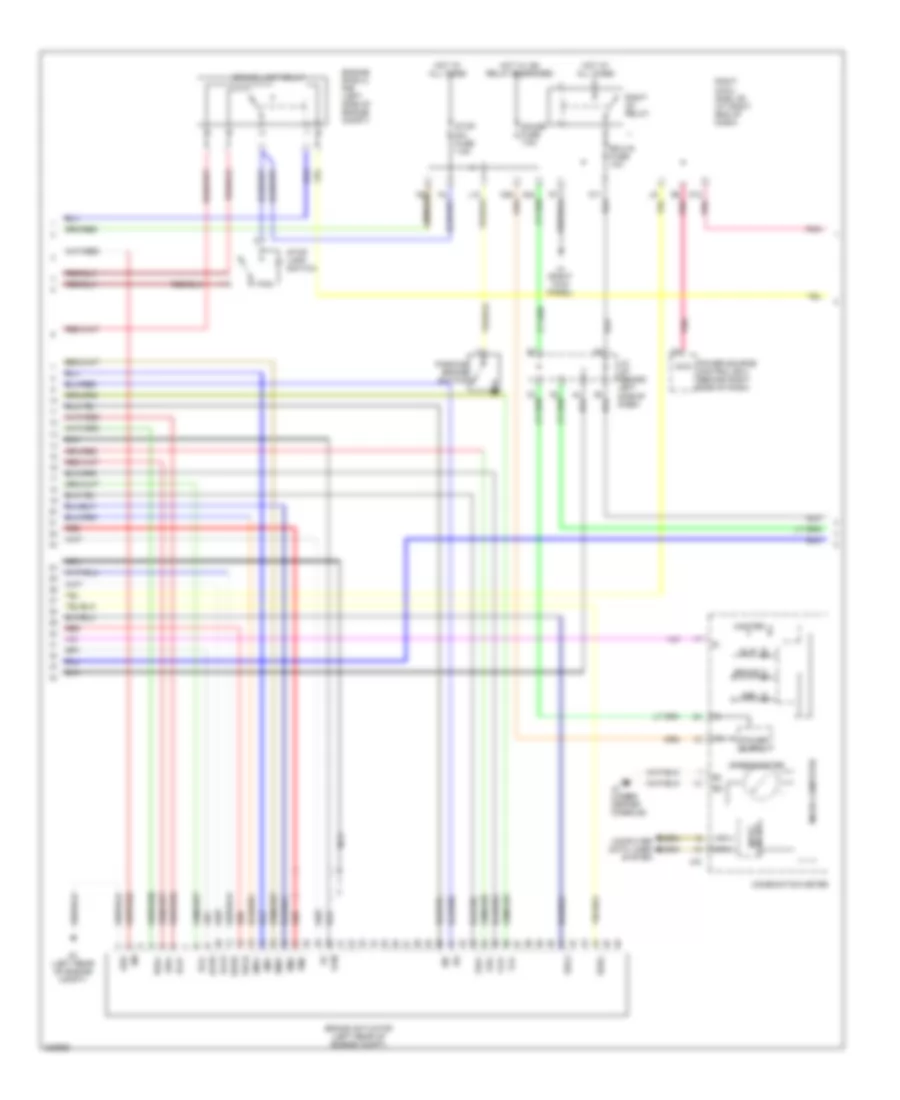
Anti-lock Brakes Wiring Diagram, without Vehicle Dynamics Integrated Management (2 of 3) for Lexus IS 350 2006
List of elements for Anti-lock Brakes Wiring Diagram, without Vehicle Dynamics Integrated Management (2 of 3) for Lexus IS 350 2006:
- A24
- A25
- A3 (left rear of engine compt)
- Abs
- Brake
- Brake actuator (left rear of engine compt)
- Brake lamp relay
- Combination meter
- Computer data lines system
- D12 pnk
- D6 pnk
- Ecu-ig fuse 10a
- Engine room 2 r/b (left side of engine compt)
- Fla+
- Fla-
- Fra+
- Fra-
- Gauge fuse 7.5a
- Grd
- Hot at all times
- Hot w/ ig2 relay energized
- Ig+
- Ig1d
- Input circuit
- J/c j27 (behind left side of dash)
- J2 (under center console)
- J34
- J4 (right kick panel)
- L10
- Master
- Micro computer
- Mpx+
- Mpx-
- Nca
- Parking brake switch
- Pmc
- Pnk
- Power source control ecu (behind right side of dash)
- Red
- Right cowl side j/b (at right end of dash)
- Right ig1 relay
- Rla+
- Rla-
- Rra+
- Rra-
- Sel2
- Sflr
- Sfrr
- Slip
- Sm1+
- Sm1-
- Sm2+
- Sm2-
- Speedometer
- Srlr
- Srrr
- Ssel
- Stop lamp switch
- Stop sw fuse 7.5a
- Vcm
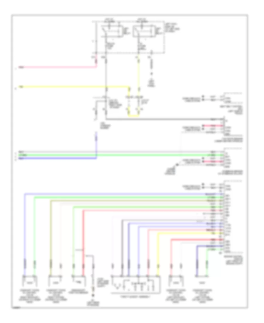
Anti-lock Brakes Wiring Diagram, without Vehicle Dynamics Integrated Management (3 of 3) for Lexus IS 350 2006
List of elements for Anti-lock Brakes Wiring Diagram, without Vehicle Dynamics Integrated Management (3 of 3) for Lexus IS 350 2006:
- Bat
- Camshaft timing oil control valve (left exhaust) (on left cylinder head)
- Camshaft timing oil control valve (left intake) (on left cylinder head)
- Camshaft timing oil control valve (right exhaust) (on right cylinder head)
- Camshaft timing oil control valve (right intake) (on right cylinder head)
- Canh
- Canl
- Computer data lines system
- Crankshaft position sensor
- D13
- D29
- E1 (left rear of engine)
- Ecu-ig fuse 10a
- Engine control module (left front of engine compt)
- Ess
- Eta
- Ge0
- Grd
- Hot at all times
- Ig fuse 10a
- J/c a7 & a8
- J/c e1 (left side of engine compt)
- J/c j70 (behind right side of dash)
- J1 (left kick panel)
- J2 (under center console)
- Left cowl side j/b (at left end of dash)
- Left ig1 relay
- Left ig2 relay
- Nca
- Ne+
- Ne-
- Oc1+
- Oc2+
- Oc2-
- Oe1+
- Oe1-
- Oe2+
- Oe2-
- Pnk
- Red
- Seat belt control ecu (left side of trunk)
- Steering sensor (at steering column)
- Throttle body assembly
- Vcta
- Vsc warning buzzer
- Vta1
- Vta2
- Yaw rate sensor (under center console)