ANTI-LOCK BRAKES
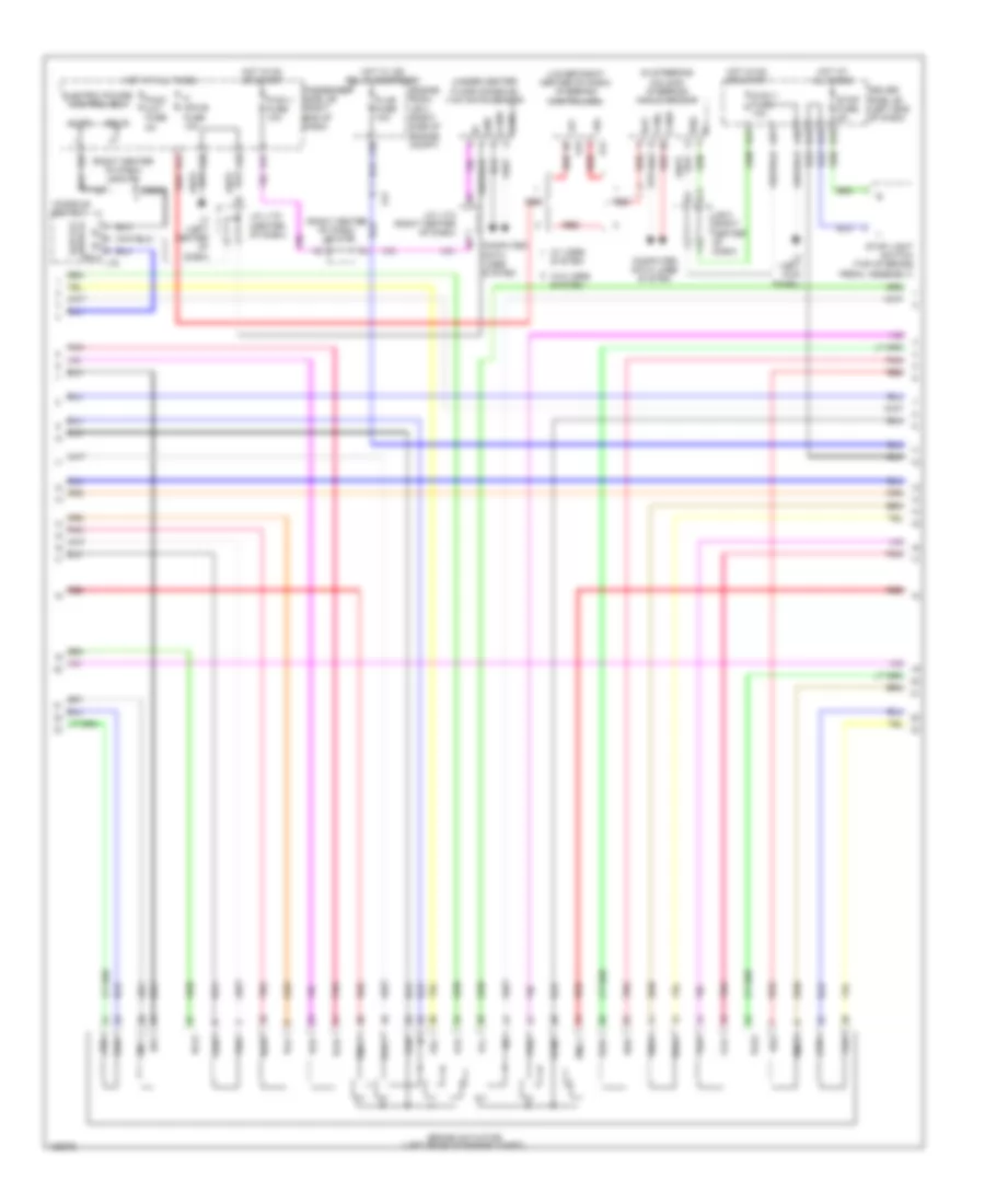
Anti-lock Brakes Wiring Diagram, with Vehicle Dynamics Integrated Management (1 of 3) for Lexus LS 460 2014

List of elements for Anti-lock Brakes Wiring Diagram, with Vehicle Dynamics Integrated Management (1 of 3) for Lexus LS 460 2014:
- (left rear corner of engine compt) a4
- +bi1
- +bi3
- A19
- A20
- A23
- A24
- A25
- A29
- A3 (left rear corner of engine compt)
- A4 (left rear corner of engine compt)
- A51
- A9 (under right headlight assembly)
- Abs main1 fuse 10a
- Abs main3 fuse 10a
- Abs mtr relay
- Abs mtr1 fuse 50a
- As1
- Brake accumulator pump (left rear of engine compt)
- Brake fluid level warning switch (brake master cylinder reservoir)
- Brake stroke sensor (above brake pedal, on bracket)
- Brake stroke simulator (left rear of engine compt)
- Bs01
- Bs03
- Buzzer
- C19
- Ca2h
- Ca2l
- Cbi1
- Computer data lines system
- Cty
- D-ig1-3 fuse 10a
- D30
- Driver side j/b (left end of dash)
- Ena
- Engine room j/b 2 (right side of engine compt)
- Engine room r/b 2 (right side of engine compt)
- Fr+
- Fr-
- Fra+
- Fra-
- Frr+
- Frr-
- G11
- G13
- G14
- Gnd
- H20
- Hot at all times
- Hot in on or start
- Ig1
- J/b 5 (right center of dash)
- J/c l172 (center of dash)
- La1
- Lbl
- Left front door courtesy switch (left "b" pillar)
- Left rear speed sensor (left rear wheel hub assembly)
- Mpx
- Mr1
- Mtt
- Outer mirror switch assembly
- Pac1
- Pck1
- Pfr
- Pmc1
- Pnk
- Prl
- R1-
- Red
- Right front speed sensor (right front wheel hub assembly)
- Rl+
- Rl-
- Rla+
- Rla-
- Rlr+
- Rlr-
- Short connector a25 & a26 (brake stroke simulator) a26 (left rear of engine compt)
- Skg
- Skid control buzzer (left end of dash)
- Skid control ecu (left rear of engine compt)
- Sks
- Sks1
- Sks2
- Smc1
- Sp1
- Vbz
- Vcm
- Vcsk
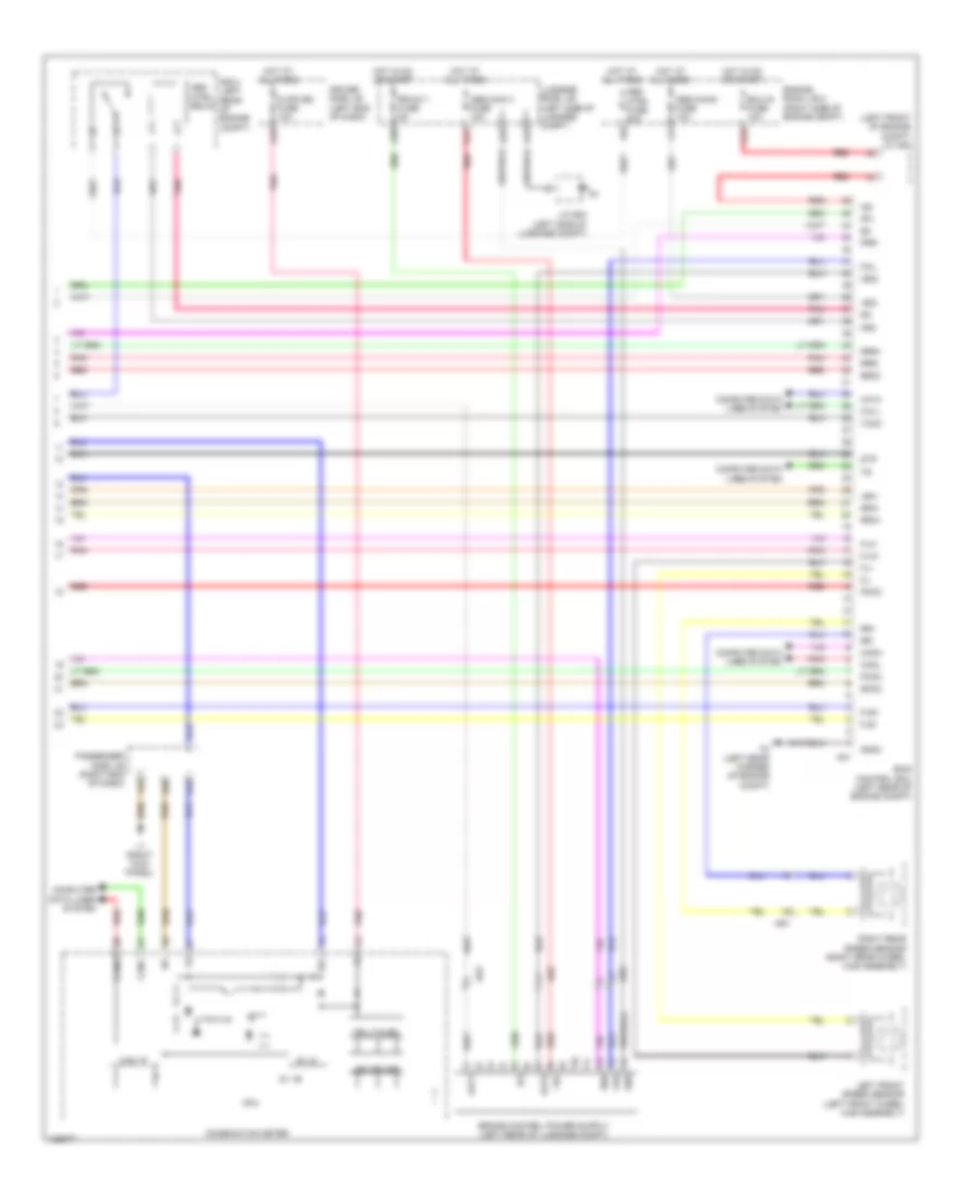
Anti-lock Brakes Wiring Diagram, with Vehicle Dynamics Integrated Management (2 of 3) for Lexus LS 460 2014
List of elements for Anti-lock Brakes Wiring Diagram, with Vehicle Dynamics Integrated Management (2 of 3) for Lexus LS 460 2014:
- (in steering column) steering angle sensor
- (lower right center of dash) steering control ecu
- (right center of dash) j/c l173
- (right center of dash) j/c l174
- (under center floor console) yaw rate sensor
- +b1
- +bo
- A21
- A31
- A39
- A40
- A41
- A42
- A57
- Bat
- Bcut
- Brake actuator (left rear of engine compt)
- Bs1
- Bs2
- C30
- Canh
- Canl
- Computer data lines system
- Console switch
- Cutd
- D-ig1-1 fuse 10a
- Driver side j/b (left end of dash)
- Electric power control ecu
- Engine room j/b 2 (right side of engine compt)
- Ess
- F12
- Fla+
- Fla-
- Flr+
- Flr-
- Fra+
- Fra-
- Frr+
- Frr-
- Gnd
- H13
- H15
- H16
- Hot at all times
- Hot in on or start
- Hot w/ ig2 relay energized
- J/b 5 (right center of dash)
- J/c l170 (center of dash)
- J/c l174 (right center of dash)
- J11
- K21
- L3 (left center of dash)
- L4 (left kick panel)
- La1
- La3
- Mpx l75
- P mpx-b fuse 10a
- P-d/c cut fuse 5a
- P-ig1-1 fuse 10a
- P-j/b fuse 10a
- Pac1
- Passenger side j/b (right end of dash)
- Pck1
- Pck2
- Pfl
- Pfr
- Pmc1
- Pmc2
- Pnk
- Prl
- Prr
- Red
- Rla+
- Rla-
- Rlr+
- Rlr-
- Rra+
- Rra-
- Rrr+
- Rrr-
- Smc1
- Smc2
- Stop fuse 5a
- Stop light switch (top of brake pedal assembly)
- Switch slip off
- System
- Vcm
- Vcm2
- W/ vgrs
- W/o vgrs system
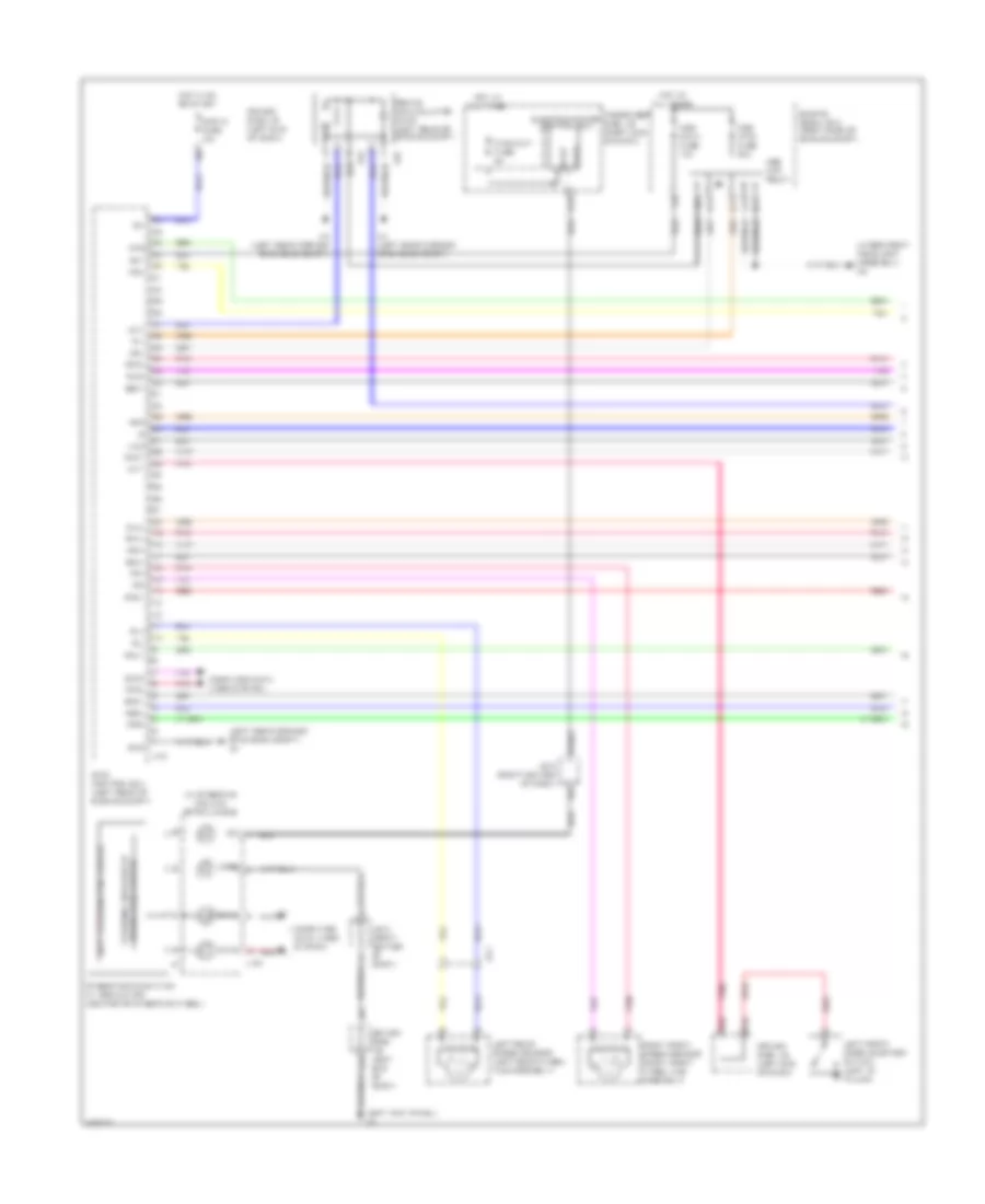
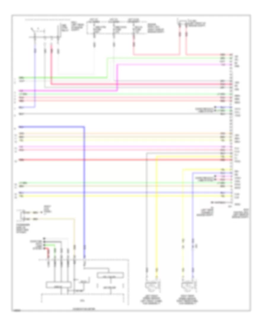
Anti-lock Brakes Wiring Diagram, with Vehicle Dynamics Integrated Management (3 of 3) for Lexus LS 460 2014
List of elements for Anti-lock Brakes Wiring Diagram, with Vehicle Dynamics Integrated Management (3 of 3) for Lexus LS 460 2014:
- (left front of engine compt) j/c a61
- +bc
- +bi2
- +bi4
- 5v +b
- 5v ic
- A17
- A18
- A21
- A3 (left rear corner of engine compt)
- A32
- A38
- A42
- A43
- A58
- Abs main 4 fuse 10a
- Abs main2 fuse 10a
- Abs mtr2 fuse 50a
- Abs mtr2 relay
- Ar1
- As2
- Bs02
- C27
- Ca1h
- Ca1l
- Can i/f
- Canh
- Canl
- Cbi2
- Combination meter
- Computer data lines system
- Cpu
- D mpx-b2 fuse 10a
- Driver side j/b (left end of dash)
- Ecu-ig fuse 10a
- Ena
- Engine room j/b 2 (right side of engine compt)
- Fail
- Fl+
- Fl-
- Fla+
- Fla-
- Flr+
- Flr-
- Gnd
- Gnd4
- Hot at all times
- Hot in on or start
- Ig1
- Ig2
- J/c s54 (left side of luggage compt)
- K13
- L1 (right kick panel)
- Led driver
- Left front speed sensor (left front wheel hub assembly)
- Luggage room j/b (left side of luggage compt)
- Mr2
- Out1
- Out2
- Passenger side j/b (right end of dash)
- Pck2
- Pfl
- Pmc2
- Pnk
- Prr
- R/b 3 (left rear of engine compt)
- R2-
- Red
- Right rear speed sensor (right rear wheel hub assembly)
- Rr+
- Rr-
- Rr-ig1-1 fuse 5a
- Rra+
- Rra-
- Rrr+
- Rrr-
- Skid control ecu (left rear of engine compt)
- Smc2
- Stp
- Telltales
- Vcm2
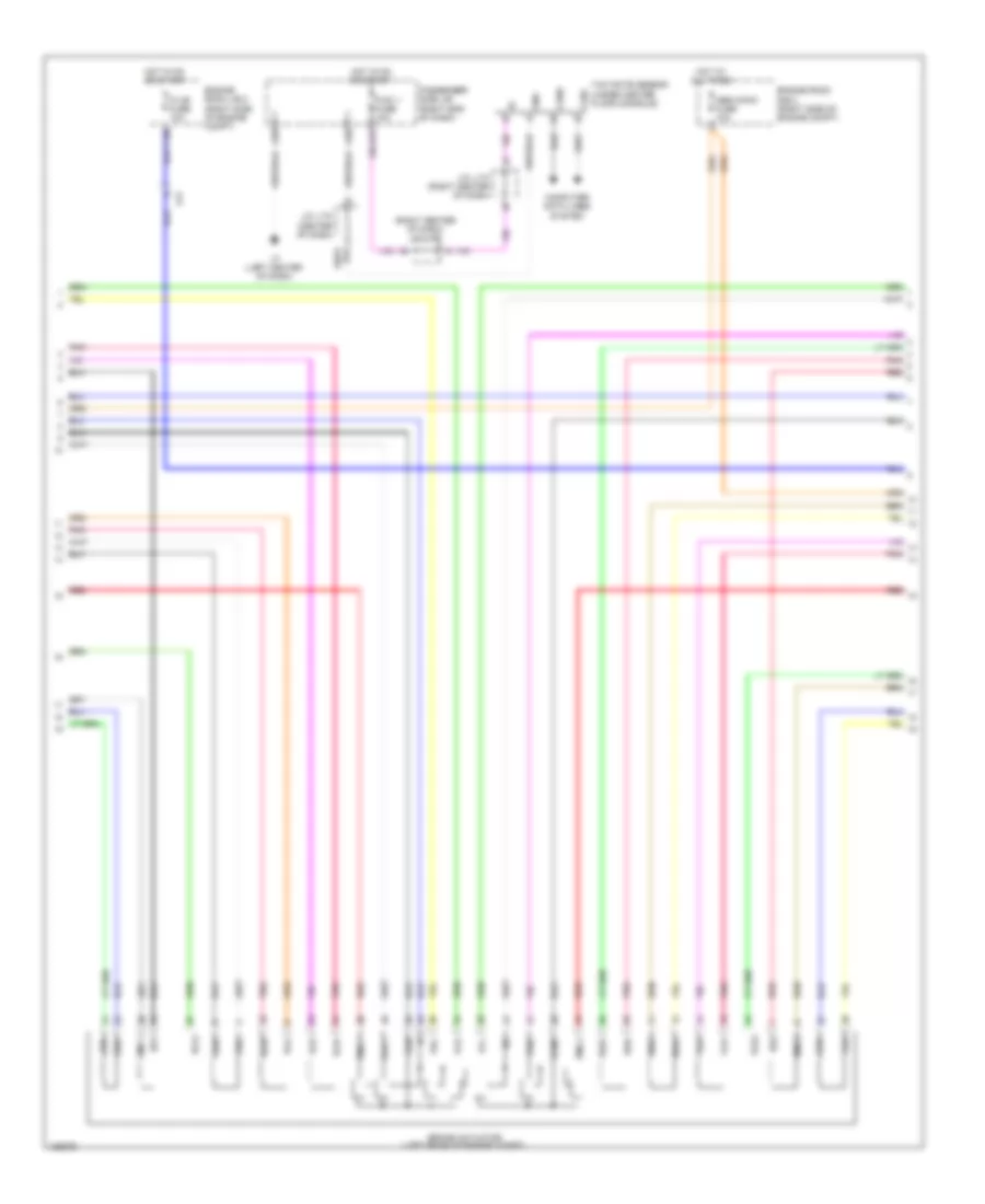
Anti-lock Brakes Wiring Diagram, without Vehicle Dynamics Integrated Management (1 of 3) for Lexus LS 460 2014
List of elements for Anti-lock Brakes Wiring Diagram, without Vehicle Dynamics Integrated Management (1 of 3) for Lexus LS 460 2014:
- (in steering column) spiral cable
- (left rear corner of engine compt) a4
- (under right headlight assembly) a9
- +bi1
- +bi3
- A19
- A23
- A24
- A3 (left rear corner of engine compt)
- A35
- A4 (left rear corner of engine compt)
- A40
- A57
- Abs main1 fuse 10a
- Abs mtr relay
- Abs mtr1 fuse 50a
- As1
- Bcut
- Brake accumulator pump (left rear of engine compt)
- Brake hold switch steering switch ecu
- Bs01
- C19
- Ca2h
- Ca2l
- Cann
- Canp
- Computer data lines system
- Cty
- Cutd
- D-ig1-3 fuse 10a
- D30
- Driver side j/b (left end of dash)
- Electric power control ecu
- Engine room j/b 2 (right side of engine compt)
- Fr+
- Fr-
- Fra+
- Fra-
- Frr+
- Frr-
- G11
- G13
- G14
- Gnd
- H20
- Hot at all times
- Hot in on or start
- Ig1
- J/b 5 (right center of dash)
- L134
- Left front door courtesy switch (left "b" pillar)
- Left rear speed sensor (left rear wheel hub assembly)
- Left steering pad switch
- Mr1
- Mtt
- Nosb
- P-d/c-cut fuse 5a
- Pac1
- Passenger side j/b (right end of dash)
- Pck1
- Pfr
- Pmc1
- Pnk
- Prl
- R1-
- Red
- Right front speed sensor (right front wheel hub assembly)
- Rl+
- Rl-
- Rla+
- Rla-
- Rlr+
- Rlr-
- Skid control ecu (left rear of engine compt)
- Smc1
- Steering pad switch w/ modulator (center of steering wheel)
- Vcm
Anti-lock Brakes Wiring Diagram, without Vehicle Dynamics Integrated Management (2 of 3) for Lexus LS 460 2014
List of elements for Anti-lock Brakes Wiring Diagram, without Vehicle Dynamics Integrated Management (2 of 3) for Lexus LS 460 2014:
- (right center of dash) j/c l173
- A31
- A39
- A40
- Abs main3 fuse 10a
- Brake actuator (left rear of engine compt)
- Bs1
- Bs2
- C30
- Canh
- Canl
- Computer data lines system
- Engine room j/b 2 (right side of engine compt)
- Engine room r/b 2 (right side of engine compt)
- Fla+
- Fla-
- Flr+
- Flr-
- Fra+
- Fra-
- Frr+
- Frr-
- Gnd
- Hot at all times
- Hot in on or start
- J/c l170 (center of dash)
- J/c l174 (right center of dash)
- L3 (left center of dash)
- La1
- P-ig1 1 fuse 10a
- P-j/b fuse 10a
- Pac1
- Passenger side j/b (right end of dash)
- Pck1
- Pck2
- Pfl
- Pfr
- Pmc1
- Pmc2
- Pnk
- Prl
- Prr
- Red
- Rla+
- Rla-
- Rlr+
- Rlr-
- Rra+
- Rra-
- Rrr+
- Rrr-
- Smc1
- Smc2
- Vcm
- Vcm2
- Yaw rate sensor (under center floor console)
Anti-lock Brakes Wiring Diagram, without Vehicle Dynamics Integrated Management (3 of 3) for Lexus LS 460 2014
List of elements for Anti-lock Brakes Wiring Diagram, without Vehicle Dynamics Integrated Management (3 of 3) for Lexus LS 460 2014:
- (right kick panel) l1
- +bi2
- +bi4
- 5v +b
- 5v ic
- A21
- A3 (left rear corner of engine compt)
- A43
- A58
- Abs main2 fuse 10a
- Abs mtr2 fuse 50a
- Abs mtr2 relay
- Ar1
- Bs02
- C27
- Ca1h
- Ca1l
- Can i/f
- Canh
- Canl
- Cann
- Canp
- Combination meter
- Computer data lines system
- Cpu
- Ecu-ig fuse 10a
- Engine room j/b 2 (right side of engine compt)
- Fl+
- Fl-
- Fla+
- Fla-
- Flr+
- Flr-
- Gnd4
- Hot at all times
- Hot in on or start
- Ig2
- J/c a61 (left front of engine compt)
- Led driver
- Left front speed sensor (left front wheel hub assembly)
- Mr2
- Passenger side j/b (right end of dash)
- Pck2
- Pfl
- Pmc2
- Pnk
- Prr
- R/b 3 (left rear of engine compt)
- R2-
- Red
- Right rear speed sensor (right rear wheel hub assembly)
- Rr+
- Rr-
- Rra+
- Rra-
- Rrr+
- Rrr-
- Skid control ecu (left rear of engine compt)
- Smc2
- Telltales
- Vcm2