ANTI-LOCK BRAKES
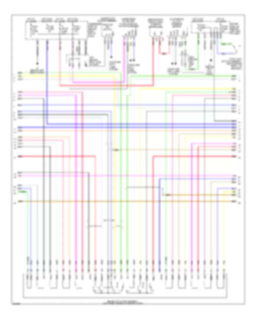
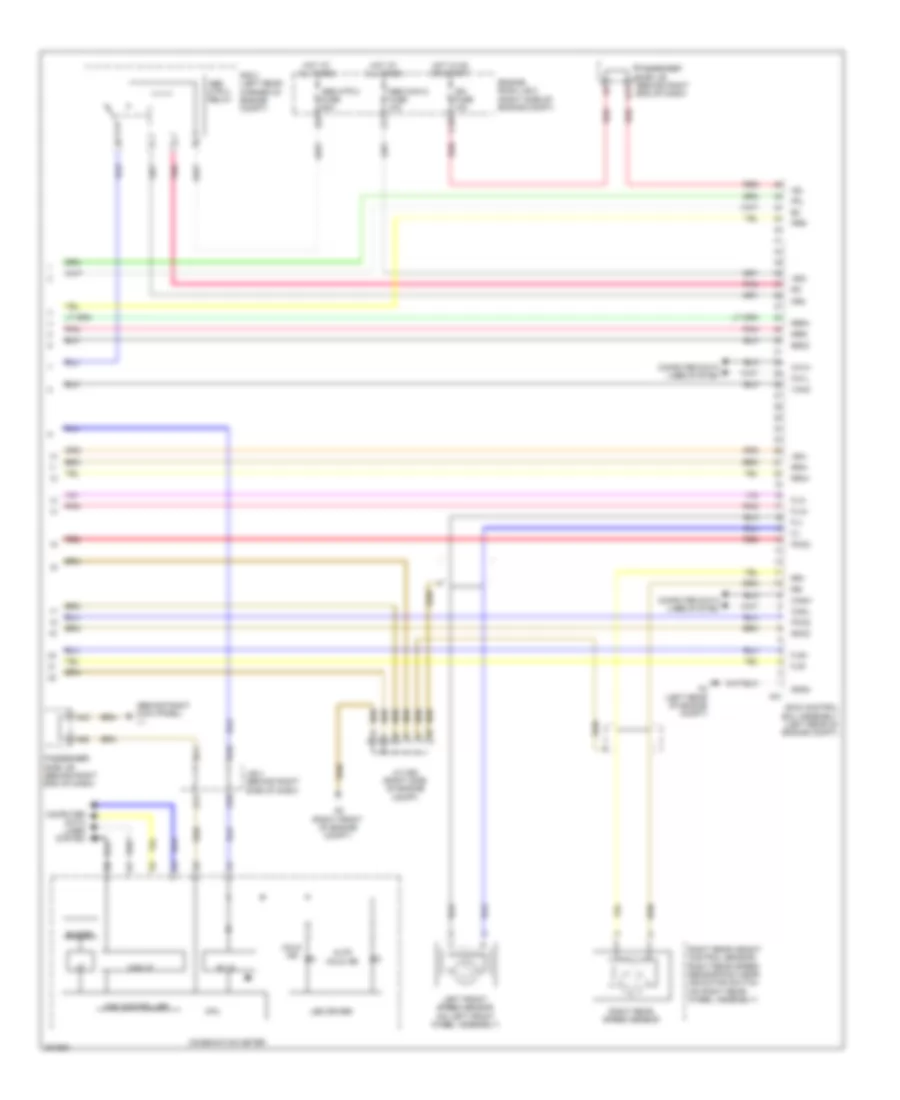
Anti-lock Brakes Wiring Diagram, with Vehicle Dynamics Integrated Management (1 of 3) for Lexus LS 600hL 2009

List of elements for Anti-lock Brakes Wiring Diagram, with Vehicle Dynamics Integrated Management (1 of 3) for Lexus LS 600hL 2009:
- (left rear of engine compt) a4
- (right front of engine compt) a8
- (right side of engine compt) j/c a64
- +bi1
- +bi3
- A19
- A20
- A23
- A25
- A3 (left rear of engine compt)
- A6 (engine compt: right rear of engine compt)
- A60
- A61
- A62
- Abs main 1 fuse 10a
- Abs main 3 fuse 10a
- Abs mtr 1 fuse 50a
- Abs mtr relay
- Brake booster pump assembly (left rear corner of engine compt) a24
- Brake fluid level warning switch (on brake master cylinder reservoir)
- Brake pedal stroke sensor assembly (above brake pedal, on bracket)
- Brake stroke simulator (left rear corner of engine compt)
- Bs01
- Bs03
- Buzzer
- C19
- Ca2h
- Ca2l
- Cbi1
- Computer data lines system
- Cty
- D-1g1 3 fuse 10a
- D30
- Driver side j/b (behind left end of dash)
- E3 (left front of engine)
- E51
- Ena
- Engine room j/b 2 (right side of engine compt)
- Engine room r/b 2 (right side of engine compt)
- Fr+
- Fr-
- Fra+
- Fra-
- Front pad wear indicator switch/ right front speed sensor (on right front wheel assembly)
- Frr+
- Frr-
- G11
- G13
- G14
- Gnd
- H10
- H20
- H21
- Hot at all times
- Hot in on or start
- Ig1
- J/c a60 & e51 (left front of engine compt)
- J/c a61 & a62 (left front of engine compt)
- J/c a70 (left front of engine compt)
- Lbl
- Left front door courtesy light switch assembly (at left "b" pillar)
- Left rear height control sensor/ left rear speed sensor (on left rear wheel assembly)
- Left rear speed sensor
- Mr1
- Mtt
- Pac1
- Pck1
- Pfr
- Pmc1
- Pnk
- Prl
- R1-
- Red
- Right front speed sensor
- Rl+
- Rl-
- Rla+
- Rla-
- Rlr+
- Rlr-
- Short connector a25 & a26 (brake stroke simulator) a26 (left rear corner of engine compt)
- Skg
- Skid control buzzer assembly (behind left end of dash)
- Skid control ecu assembly (left rear of engine compt)
- Sks
- Sks1
- Sks2
- Smc1
- Sp1
- Vbz
- Vcm
- Vcsk
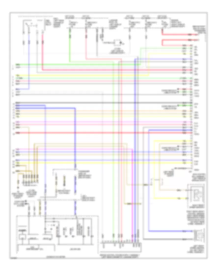
Anti-lock Brakes Wiring Diagram, with Vehicle Dynamics Integrated Management (2 of 3) for Lexus LS 600hL 2009
List of elements for Anti-lock Brakes Wiring Diagram, with Vehicle Dynamics Integrated Management (2 of 3) for Lexus LS 600hL 2009:
- (behind right side of dash) steering control ecu
- (in steering column) steering sensor
- (under rear of center floor console) yaw rate sensor
- +bi
- +bo
- A12
- A21
- A31
- A39
- A40
- A41
- A42
- A51
- A57
- A60
- B12
- Bat
- Brake actuator assembly (left rear corner of engine compt)
- Bs1
- Bs2
- Ca1h
- Ca1l
- Combination switch assembly
- Computer data lines system
- D-ig1-1 fuse 5a
- Driver side j/b (behind left end of dash)
- Ess
- F12
- Fla+
- Fla-
- Flr+
- Flr-
- Fra+
- Fra-
- Frr+
- Frr-
- Gnd
- H12
- H13
- H15
- H16
- Hot at all times
- Hot in on or start
- J/b 4 (behind right side of dash)
- J/b 5 (behind left side of dash)
- J11
- K21
- L3 (behind left side of dash)
- L4 (behind left kick panel)
- Mpx
- P ig2 fuse 5a
- P mpx-b fuse 10a
- P-d/c cut fuse 5a
- P-ig1 1 fuse 10a
- Pac1
- Passenger side j/b (behind right end of dash)
- Pck1
- Pck2
- Pfl
- Pfr
- Pmc1
- Pmc2
- Pnk
- Prl
- Prr
- Red
- Rla+
- Rla-
- Rlr+
- Rlr-
- Rra+
- Rra-
- Rrr+
- Rrr-
- Smc1
- Smc2
- Stop fuse 5a
- Stop light switch assembly (above brake pedal, on bracket)
- Traction off switch
- Vcm
- Vcm2
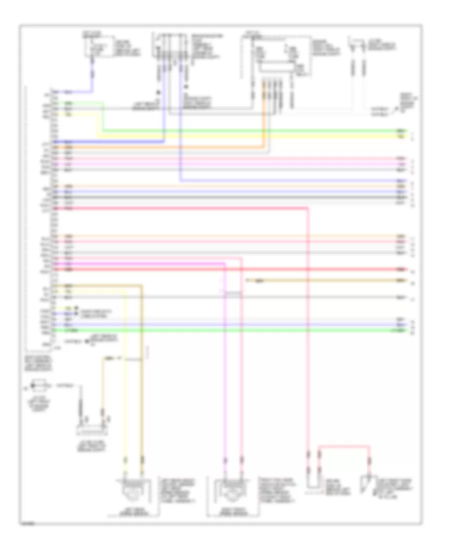
Anti-lock Brakes Wiring Diagram, with Vehicle Dynamics Integrated Management (3 of 3) for Lexus LS 600hL 2009
List of elements for Anti-lock Brakes Wiring Diagram, with Vehicle Dynamics Integrated Management (3 of 3) for Lexus LS 600hL 2009:
- (behind right end of dash) passenger side j/b
- +bc
- +bi2
- +bi4
- 5v ic
- A17
- A18
- A21
- A3 (left rear of engine compt)
- A32
- A38
- A43
- A58
- A8 (right front of engine compt)
- Abs ind
- Abs main 2 fuse 10a
- Abs main 4 fuse 10a
- Abs mtr 2 fuse 50a
- Abs mtr 2 relay
- Brake ind
- Bs02
- Buzzer
- C18
- Ca1h
- Ca1l
- Can controller
- Can i/f
- Canh
- Canl
- Cbi2
- Combination meter
- Computer data lines system
- Controlled electronically
- Cpu
- Ena
- Engine room j/b 2 (right side of engine compt)
- Fail
- Fl+
- Fl-
- Fla+
- Fla-
- Flr+
- Flr-
- G10
- G11
- Gnd
- Gnd4
- H10
- H11
- Hot at all times
- Hot in on or start
- I/f
- Ig1
- Ig2
- Ign fuse 10a
- J/b 4 (behind right side of dash)
- J/c a80 (right side of engine compt)
- J/c s54 (left side of luggage compt)
- K13
- K17
- L1 (behind right kick panel)
- Led driver
- Left front speed sensor (on left front wheel assembly)
- Luggage room j/b (left side of luggage compt)
- Master ind
- Mr2
- Out1
- Out2
- Passenger side j/b (behind right end of dash)
- Pck2
- Pfl
- Pmc2
- Pnk
- Prr
- R/b 3 (left rear corner of engine compt)
- R2-
- Red
- Right rear height control sensor/ right rear speed sensor/pad wear indicator switch (on right rear wheel assembly)
- Right rear speed sensor
- Rr+
- Rr-
- Rr-ig1-1 fuse 5a
- Rra+
- Rra-
- Rrr+
- Rrr-
- Skid control ecu assembly (left rear of engine compt)
- Slip ind
- Smc2
- Stp
- Vcm2
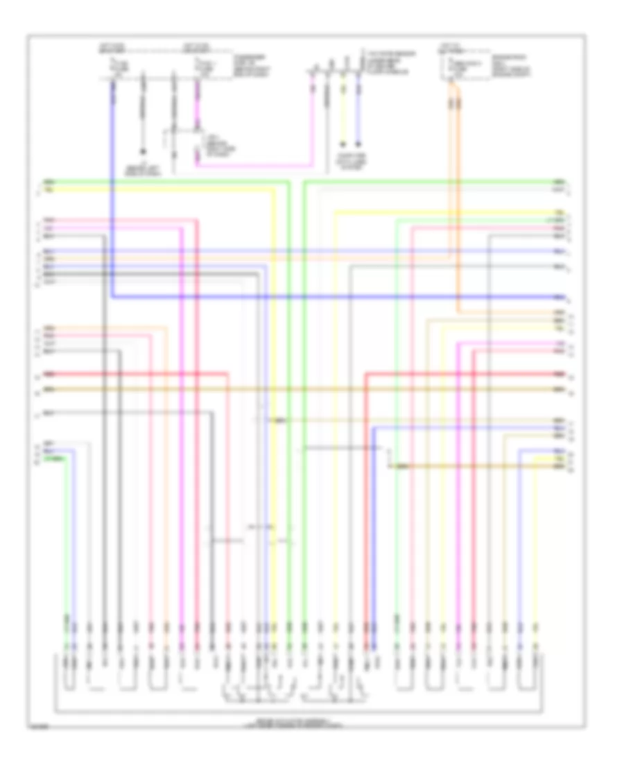
Anti-lock Brakes Wiring Diagram, without Vehicle Dynamics Integrated Management (1 of 3) for Lexus LS 600hL 2009
List of elements for Anti-lock Brakes Wiring Diagram, without Vehicle Dynamics Integrated Management (1 of 3) for Lexus LS 600hL 2009:
- (left rear of engine copmt) a4
- (right front of engine compt) a8
- +bi1
- +bi3
- A19
- A23
- A3 (left rear of engine compt)
- A6 (engine compt: right rear of engine compt)
- A61
- A62
- Abs main 1 fuse 10a
- Abs mtr 1 fuse 50a
- Abs mtr relay
- Brake booster pump assembly (left rear corner of engine compt) a24
- Bs01
- C19
- Ca2h
- Ca2l
- Computer data lines system
- Cty
- D-1g1 3 fuse 10a
- D30
- Driver side j/b (behind left end of dash)
- Engine room j/b 2 (right side of engine compt)
- Fr+
- Fr-
- Fra+
- Fra-
- Front pad wear indicator switch/ right front speed sensor (on right front wheel assembly)
- Frr+
- Frr-
- G11
- G13
- G14
- Gnd
- H20
- Hot at all times
- Hot in on or start
- Ig1
- J/c a61 & a62 (left front of engine compt)
- J/c a64 (right side of engine compt)
- J/c a70 (left front of engine compt)
- Left front door courtesy light switch assembly (at left "b" pillar)
- Left rear height control sensor/ left rear speed sensor (on left rear wheel assembly)
- Left rear speed sensor
- Mr1
- Mtt
- Pac1
- Pck1
- Pfr
- Pmc1
- Pnk
- Prl
- R1-
- Red
- Right front speed sensor
- Rl+
- Rl-
- Rla+
- Rla-
- Rlr+
- Rlr-
- Skid control ecu assembly (left rear of engine compt)
- Smc1
- Vcm
Anti-lock Brakes Wiring Diagram, without Vehicle Dynamics Integrated Management (2 of 3) for Lexus LS 600hL 2009
List of elements for Anti-lock Brakes Wiring Diagram, without Vehicle Dynamics Integrated Management (2 of 3) for Lexus LS 600hL 2009:
- (under rear of center floor console)
- A31
- A39
- A51
- A60
- Abs main 3 fuse 10a
- B12
- Brake actuator assembly (left rear corner of engine compt)
- Bs1
- Bs2
- Ca1h
- Ca1l
- Computer data lines system
- Engine room r/b 2 (right side of engine compt)
- Fla+
- Fla-
- Flr+
- Flr-
- Fra+
- Fra-
- Frr+
- Frr-
- Gnd
- H12
- Hot at all times
- Hot in on or start
- J/b 4 (behind right side of dash)
- L3 (behind left side of dash)
- P ig2 fuse 5a
- P-ig1 1 fuse 10a
- Pac1
- Passenger side j/b (behind right end of dash)
- Pck1
- Pck2
- Pfl
- Pfr
- Pmc1
- Pmc2
- Pnk
- Prl
- Prr
- Red
- Rla+
- Rla-
- Rlr+
- Rlr-
- Rra+
- Rra-
- Rrr+
- Rrr-
- Smc1
- Smc2
- Vcm
- Vcm2
- Yaw rate sensor
Anti-lock Brakes Wiring Diagram, without Vehicle Dynamics Integrated Management (3 of 3) for Lexus LS 600hL 2009
List of elements for Anti-lock Brakes Wiring Diagram, without Vehicle Dynamics Integrated Management (3 of 3) for Lexus LS 600hL 2009:
- (behind right kick panel) l1
- +bi2
- +bi4
- 5v ic
- A21
- A3 (left rear of engine compt)
- A43
- A58
- A8 (right front of engine compt)
- Abs main 2 fuse 10a
- Abs mtr 2 fuse 50a
- Abs mtr 2 relay
- Auto hold ind
- Bs02
- Buzzer
- C18
- Ca1h
- Ca1l
- Can controller
- Can i/f
- Canh
- Canl
- Combination meter
- Computer data lines system
- Cpu
- Engine room j/b 2 (right side of engine compt)
- Fl+
- Fl-
- Fla+
- Fla-
- Flr+
- Flr-
- G10
- G11
- Gnd4
- H10
- H11
- Hold ind
- Hot at all times
- Hot in on or start
- I/f
- Ig2
- Ign fuse 10a
- J/b 4 (behind right side of dash)
- J/c a80 (right side of engine compt)
- K17
- Led driver
- Left front speed sensor (on left front wheel assembly)
- Mr2
- Passenger side j/b (behind right end of dash)
- Pck2
- Pfl
- Pmc2
- Pnk
- Prr
- R/b 3 (left rear corner of engine compt)
- R2-
- Red
- Right rear height control sensor/ right rear speed sensor/pad wear indicator switch (on right rear wheel assembly)
- Right rear speed sensor
- Rr+
- Rr-
- Rra+
- Rra-
- Rrr+
- Rrr-
- Skid control ecu assembly (left rear of engine compt)
- Smc2
- Vcm2