ANTI-LOCK BRAKES
Anti-lock Brake Wiring Diagrams for Lincoln Continental 1997
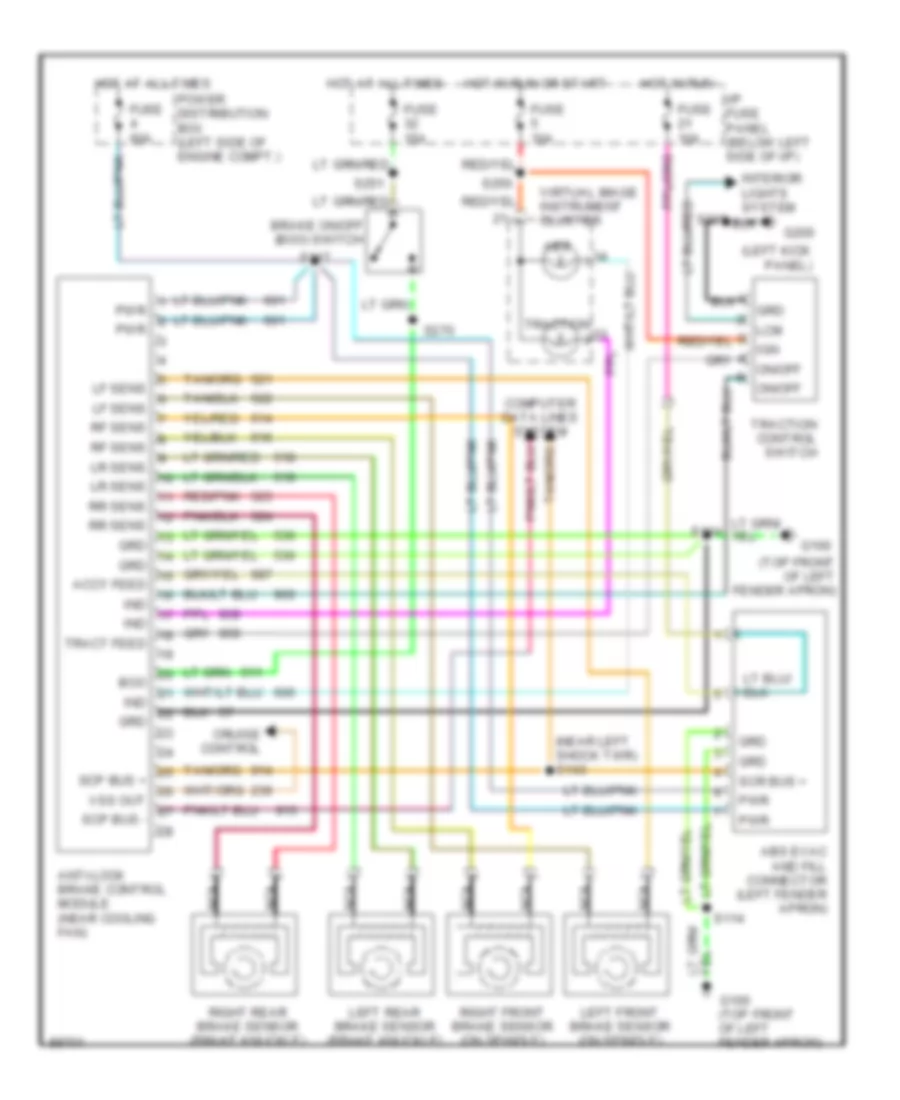
List of elements for Anti-lock Brake Wiring Diagrams for Lincoln Continental 1997:
- (left kick panel)
- (near left shock twr) s143
- (top front of left fender apron)
- Abs
- Abs evac and fill connector (left fender apron)
- Accy feed
- Anti-lock brake control module (near cooling fan)
- Boo
- Brake on/off (boo) switch
- Computer data lines system
- Cruise control
- Fuse 10a
- Fuse 15a
- Fuse 60a
- G100
- G100 (top front of left fender apron)
- G200
- Grd
- Hot at all times
- Hot in run
- Hot in run or start
- I/p fuse panel (below left side of i/p)
- Ign
- Ind
- Interior lights system
- Lcm
- Left front brake sensor (on spindle)
- Left rear brake sensor (brake knuckle)
- Lf sens
- Lr sens
- Nca
- On/off
- Power distribution box (left side of engine compt.)
- Pwr
- Red/pnk
- Rf sens
- Right front brake sensor (on spindle)
- Right rear brake sensor (brake knuckle)
- Rr sens
- S114
- S117
- S219
- S250
- S251
- S270
- Scp bus +
- Scp bus -
- Scr bus +
- Tract feed
- Traction
- Traction control switch
- Virtual image instrument cluster
- Vss out
 English