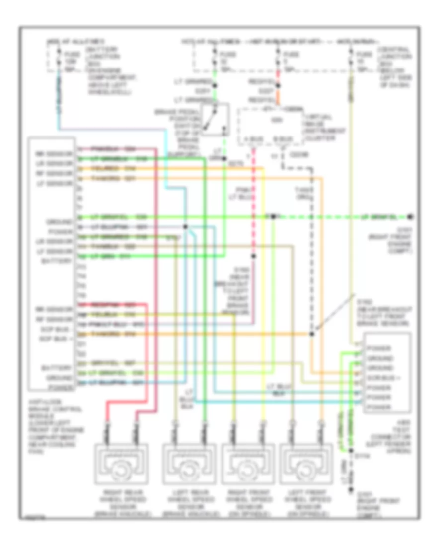
ANTI-LOCK BRAKES
Anti-lock Brake Wiring Diagrams for Lincoln Continental 2002
List of elements for Anti-lock Brake Wiring Diagrams for Lincoln Continental 2002:
- A bus -
- Abs test connector (left fender apron)
- Anti-lock brake control module (lower left front of engine compartment, near cooling fan)
- B bus +
- Battery
- Battery junction box (in engine compartment, above left wheelwell)
- Brake pedal position switch (top of brake pedal support)
- C220a
- C220b
- Central junction box (below left side of dash)
- Fuse 10a
- Fuse 12m 60a
- Fuse 15a
- G101 (right front engine compt)
- Ground
- Hot at all times
- Hot in run
- Hot in run or start
- Ign
- Left front wheel speed sensor (on spindle)
- Left rear wheel speed sensor (brake knuckle)
- Lf sensor
- Lr sensor
- Nca
- Power
- Red/pnk
- Rf sensor
- Right front wheel speed sensor (on spindle)
- Right rear wheel speed sensor (brake knuckle)
- Rr sensor
- S114
- S117
- S160 (near breakout to left front brake sensor)
- S162 (near breakout to left front brake sensor)
- S227
- S251
- S270
- Scp bus +
- Scp bus -
- Scr bus +
- Virtual image instrument cluster
 English