ANTI-LOCK BRAKES
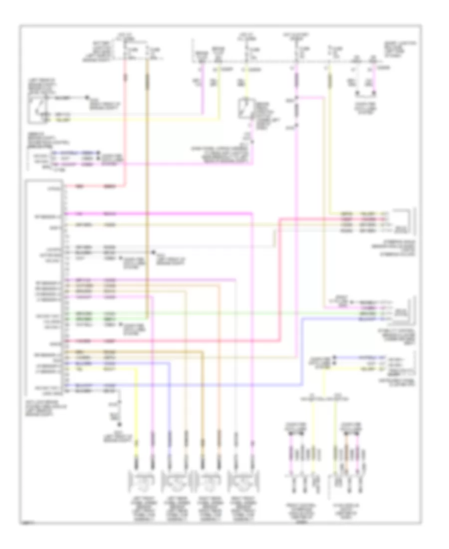
Anti-lock Brakes Wiring Diagram for Lincoln MKS 2009
List of elements for Anti-lock Brakes Wiring Diagram for Lincoln MKS 2009:
- (left rear of engine compt) brake fluid level switch
- (rear of engine compt) powertrain control module (pcm)
- (right "c" pillar) g303
- Anti-lock brake system (abs) module (left rear of engine compt)
- Battery junction box (bjb) (left side of engine compt)
- Bps
- Brake fluid sw
- Brake fluid sw rtn
- Brake pedal position switch (under left side of dash)
- C175b
- C2280b
- C2280d
- C2280f
- C228a
- C228c
- Cbp34
- Cbp35
- Cca15
- Ccb08
- Computer data lines system
- Front control interface module (fcim) (center of dash)
- Fuse 10a
- Fuse 15a
- Fuse 20a
- Fuse 40a
- Fuse 5a
- G100 (right front of engine compt)
- G101 (left front of engine compt)
- Gd120
- Hot at all times
- Hot in start or run
- Hs can +
- Hs can -
- Hs can yaw +
- Hs can yaw -
- Hvac module (datc) (center of dash)
- Instrument panel cluster (ipc)
- Ivd rtn
- Left front wheel speed sensor (left front wheel hub assembly)
- Left rear wheel speed sensor (left rear wheel hub assembly)
- Lf sensor hi
- Lf sensor lo
- Logic gnd
- Lr sensor hi
- Lr sensor lo
- Motor gnd
- Ms can +
- Ms can -
- Ms canh
- Ms canl
- Mtr b+
- Nca
- Rca17
- Rca18
- Rca19
- Rca20
- Rcs06
- Red
- Rf sensor hi
- Rf sensor lo
- Right front wheel speed sensor (right front wheel hub assembly)
- Right rear wheel speed sensor (right rear wheel hub assembly)
- Rr sensor hi
- Rr sensor lo
- Run
- S102
- S108
- S111 (dash panel wiring harness, to headlamp junction near breakout to left rear of engine compt)
- S204
- Sas a
- Sas b
- Sbb09
- Sbb12
- Smart junction box (sjb) (left side of dash)
- Solid state
- Stability control sensor cluster (under driver's seat)
- Steering angle sensor module (sasm) (top of steering column)
- Trac cont
- Trac cont sw
- Traction ctl on/off
- Valve b+
- Vca03
- Vca04
- Vca05
- Vca06
- Vca23
- Vca24
- Vcs06
- Vcs07
- Vdb04
- Vdb05
- Vdb06
- Vdb07
- W/ navigation
- W/o navigation
 English