ANTI-LOCK BRAKES
Anti-lock Brakes Wiring Diagram for Lincoln Town Car Signature 2003
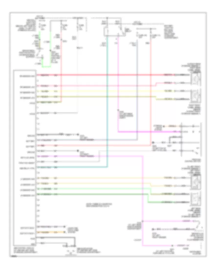
List of elements for Anti-lock Brakes Wiring Diagram for Lincoln Town Car Signature 2003:
- (in left front of brake assembly) left front wheel speed sensor
- (in right rear of brake assembly) right rear wheel speed sensor
- Abs control module (at center left side of engine compartment)
- Abs pump motor (at center left side of engine compartment)
- Abs relay
- Abs relay ctrl
- Battery
- Battery junction box (bjb) (at right front side of engine compartment)
- Bk fluid level
- Brake fluid level switch (on brake fluid reservoir)
- Brake pedal position switch (on brake pedal support)
- C220b
- Computer data lines syetem
- Forward of "a" pillar)
- Fuse 106 40a
- Fuse 10a
- Fuse 118 20a
- Fuse 20a
- Fuse 7.5a
- G102 (at left front fender)
- G107 (at right front fender)
- G208 (at bottom of left "a" pillar)
- Gnd
- Ground
- Hot at all times
- Hot at all times central junction box (cjb) (behind left side of dash, to left of steering column)
- Hot in run
- Instrument cluster
- Interior lights system
- Left rear wheel speed sensor (in left rear of brake assembly)
- Lf sensor high
- Lr sensor high
- Lr sensor low
- Nca
- Note: there is a shorting bar across pins 15 & 16
- Pwr
- Red
- Red/pnk
- Rf sensor high
- Rf sensor low
- Right front wheel speed sensor (in right front of brake assembly)
- Rr sensor high
- Rr sensor low
- S108
- S137
- S164 (at left rear side of engine compartment)
- S169 (at left rear side of engine compt)
- S177
- S207
- S234
- S241 (at left footwell, forward of "a" pillar)
- S243 (at left footwell,
- S253
- Scp data bus +
- Scp data bus -
- Traction assist
- Traction control switch
- Vpwr
 English