ANTI-LOCK BRAKES
Anti-lock Brakes Wiring Diagram, with Dynamic Stability Control for Mazda 3 i Sport 2008

List of elements for Anti-lock Brakes Wiring Diagram, with Dynamic Stability Control for Mazda 3 i Sport 2008:
- 0922-101a
- Abs 1 fuse 30a
- Abs 2 fuse 20a
- Abs ig fuse 10a
- Brake ind
- Combined sensor (under front passenger's seat)
- Computer data lines system
- Dsc hydraulic unit control module (at left rear of engine compt)
- Dsc ind
- Dsc off ind
- Dsc off switch
- Fuse & relay box (left rear of engine compt)
- G1 (behind left headlight)
- G8 (behind right end of dash)
- Hot at all times
- Hot in run or start
- Ill
- Instrument cluster
- Interior lights system
- J-03
- Left front abs wheel speed sensor (on left front wheel)
- Left rear abs wheel speed sensor (on left rear wheel)
- Meter fuse 10a
- Micro-computer
- Passenger junction box (behind right side of dash)
- Red
- Right front abs wheel speed sensor (on right front wheel)
- Right rear abs wheel speed sensor (on right rear wheel)
- Steering angle sensor (on steering column)
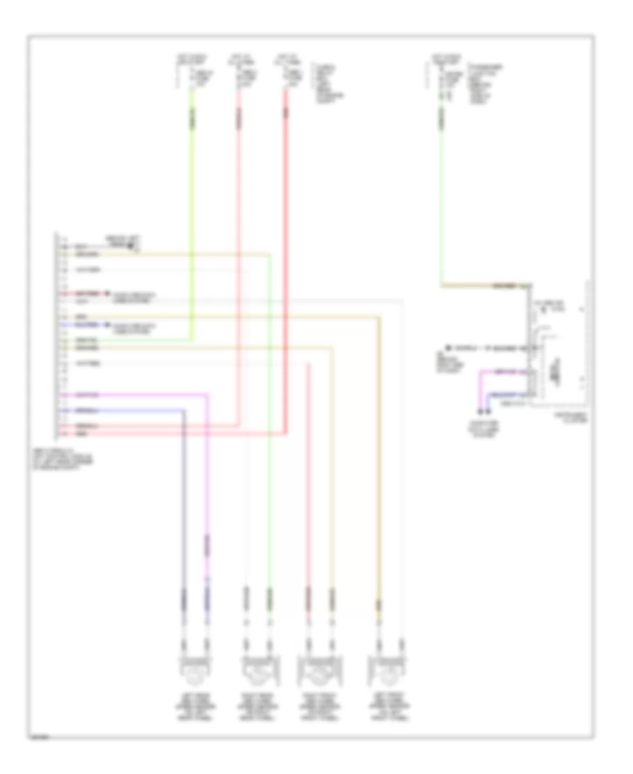
Anti-lock Brakes Wiring Diagram, without Dynamic Stability Control for Mazda 3 i Sport 2008
List of elements for Anti-lock Brakes Wiring Diagram, without Dynamic Stability Control for Mazda 3 i Sport 2008:
- (behind left headlight) g1
- (on left front wheel)
- 0922-101a
- 4w abs ind
- Abs 1 fuse 30a
- Abs 2 fuse 20a
- Abs hydraulic unit control module (at left rear corner of engine compt)
- Abs ig fuse 10a
- Computer data lines system
- Fuse & relay box (left rear of engine compt)
- G8 (behind right end of dash)
- Hot at all times
- Hot in run or start
- Instrument cluster
- J-03
- Left front abs wheel speed sensor
- Left rear abs wheel speed sensor (on left rear wheel)
- Meter fuse 10a
- Micro- computer
- Passenger junction box (behind right side of dash)
- Red
- Right front abs wheel speed sensor (on right front wheel)
- Right rear abs wheel speed sensor (on right rear wheel)