ANTI-LOCK BRAKES
Anti-lock Brakes Wiring Diagram, with Dynamic Stability Control for Mazda 3 i Sport 2013

List of elements for Anti-lock Brakes Wiring Diagram, with Dynamic Stability Control for Mazda 3 i Sport 2013:
- 0415-08
- 0415-09
- 0415-10
- 0810-01b
- 0922-101b
- 0940-01a
- 0940-01b
- 2aa
- 4w abs
- Abs fuse 40a
- Abs ig fuse 7.5a
- Bcm (under left side of dash)
- Brake fluid level sensor (in brake fluid reservoir)
- Brake ind
- Brake switch (behind left side of dash)
- C-02
- C-03
- C-04
- C-06
- C-36
- Computer data lines system
- Door locks system
- Dsc fuse 20a
- Dsc hu/cm (left rear of engine compt)
- Dsc ind
- Dsc off ind
- Dsc off switch
- Fuse block
- G02 (behind left headlight)
- G02 (mzr) g03 (skyactiv) (mzr: behind left headlight) (skyactive: behind right headlight)
- G06 (left rear of engine)
- G08 (under left end of dash)
- Hot at all times
- Hot in on or start
- Ill
- Instrument cluster
- Interior lights system
- J/c c-45 (left end of dash)
- J/c c-47 (center left of dash)
- Left front abs wheel speed sensor (on left front wheel)
- Left rear abs wheel speed sensor (on left rear wheel)
- Meter fuse 15a
- Microcomputer
- Parking brake switch (at base of parking brake lever)
- Pnk
- Red
- Relay & fuse block (left rear of engine compt)
- Right front abs wheel speed sensor (on right front wheel)
- Right rear abs wheel speed sensor (on right rear wheel)
- Sas control module (under center console)
- Steering angle sensor (on steering column)
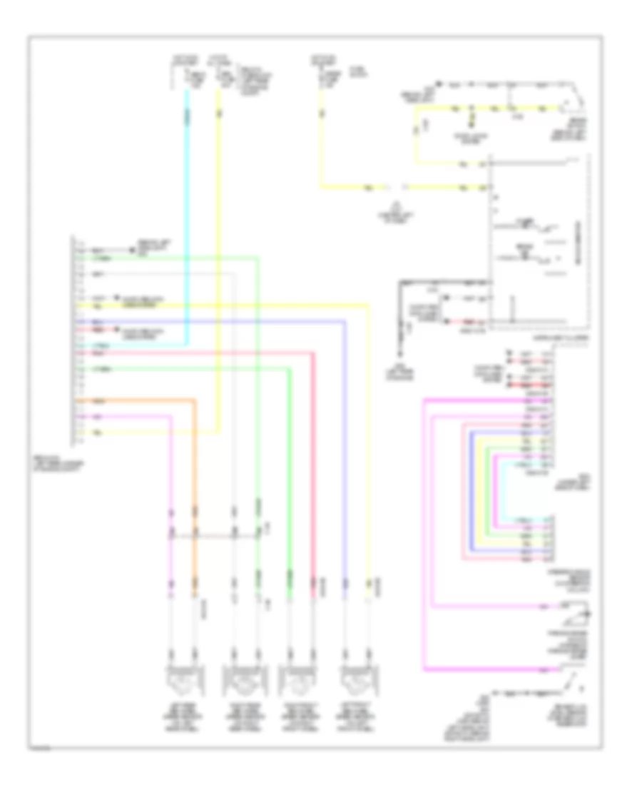
Anti-lock Brakes Wiring Diagram, without Dynamic Stability Control for Mazda 3 i Sport 2013
List of elements for Anti-lock Brakes Wiring Diagram, without Dynamic Stability Control for Mazda 3 i Sport 2013:
- (behind left headlight) g02
- (on left front wheel)
- 0413-08
- 0413-09
- 0413-10
- 0922-101b
- 0940-01a
- 0940-01b
- 4w abs
- Abs fuse 40a
- Abs hu/cm (left rear corner of engine compt)
- Abs ig fuse 7.5a
- Bcm (under left side of dash)
- Brake fluid level sensor (in brake fluid reservoir)
- Brake ind
- Brake switch (behind left side of dash)
- C-02
- C-03
- C-04
- C-06
- C-36
- Computer data lines system
- Door locks system
- Fuse block
- G02 (behind left headlight)
- G02 (mzr) g03 (skyactiv) (mzr: behind left headlight) (skyactiv: behind right headlight)
- G06 (left rear of engine)
- Hot at all times
- Hot in on or start
- Instrument cluster
- J/c c-47 (center left of dash)
- Left front abs wheel speed sensor
- Left rear abs wheel speed sensor (on left rear wheel)
- Meter fuse 15a
- Microcomputer
- Parking brake switch (at base of parking brake lever)
- Pnk
- Red
- Relay & fuse block (left rear of engine compt)
- Right front abs wheel speed sensor (on right front wheel)
- Right rear abs wheel speed sensor (on right rear wheel)
- Steering angle sensor (on steering column)