
ANTI-LOCK BRAKES
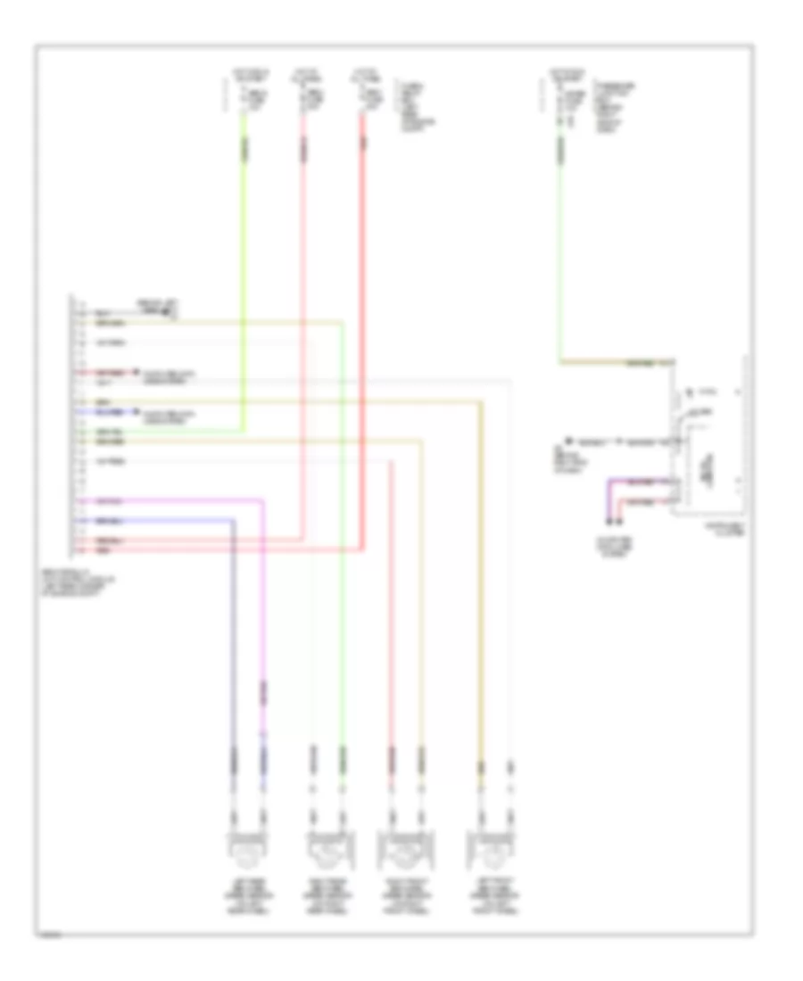
Anti-lock Brakes Wiring Diagram for Mazda 3 s 2004
List of elements for Anti-lock Brakes Wiring Diagram for Mazda 3 s 2004:
ANTI-LOCK BRAKESCOMPUTER DATA LINESDEFOGGERSAIR CONDITIONINGCRUISE CONTROLANTI-THEFTEXTERIOR LIGHTSENGINE PERFORMANCEELECTRONIC POWER STEERINGGROUND DISTRIBUTIONCOOLING FANHEADLIGHTSINTERIOR LIGHTSHORNPOWER TOP/SUNROOFNAVIGATIONPOWER MIRRORSINSTRUMENT CLUSTERPOWER DISTRIBUTIONSHIFT INTERLOCKSUPPLEMENTAL RESTRAINTSPOWER WINDOWSRADIOWARNING SYSTEMSTRANSMISSIONSTARTING/CHARGINGWIPER/WASHER