
ANTI-LOCK BRAKES
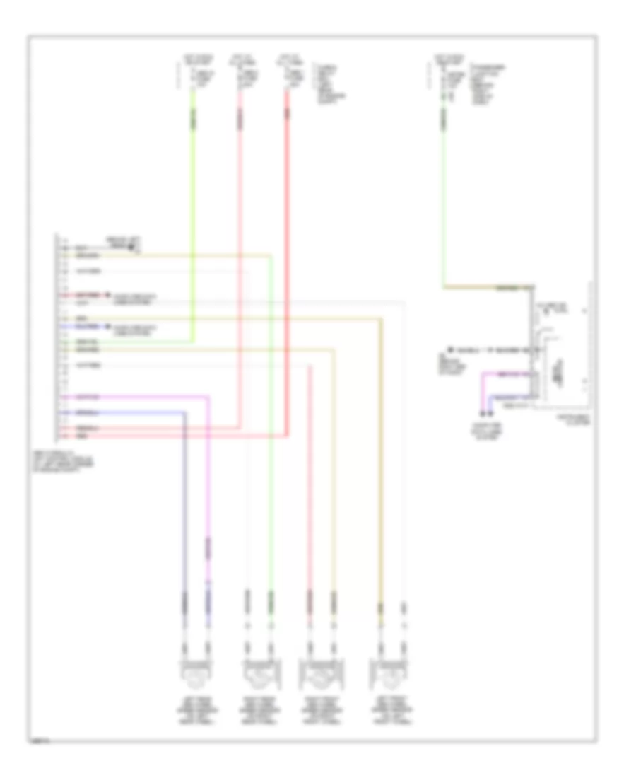
Anti-lock Brakes Wiring Diagram for Mazda 3 s 2006
List of elements for Anti-lock Brakes Wiring Diagram for Mazda 3 s 2006:
COOLING FANANTI-LOCK BRAKESANTI-THEFTAIR CONDITIONINGELECTRONIC POWER STEERINGCOMPUTER DATA LINESDEFOGGERSCRUISE CONTROLHORNGROUND DISTRIBUTIONINSTRUMENT CLUSTERENGINE PERFORMANCEEXTERIOR LIGHTSHEADLIGHTSINTERIOR LIGHTSPOWER DISTRIBUTIONPOWER MIRRORSNAVIGATIONPOWER DOOR LOCKSPOWER SEATSSHIFT INTERLOCKPOWER TOP/SUNROOFPOWER WINDOWSTRANSMISSIONSTARTING/CHARGINGRADIOSUPPLEMENTAL RESTRAINTSWARNING SYSTEMSWIPER/WASHER