ANTI-LOCK BRAKES
Anti-lock Brakes Wiring Diagram for Mazda 5 Grand Touring 2013
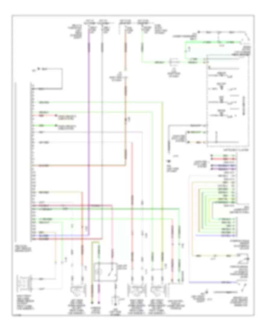
List of elements for Anti-lock Brakes Wiring Diagram for Mazda 5 Grand Touring 2013:
- 0810-101b
- 0940-101a
- 0940-101c
- 0940-101f
- Abs ind
- Abs p fuse 40a
- Abs v fuse 20a
- Bcm (under right center of dash)
- Brake fluid level sensor (in brake fluid reservoir)
- Brake ind
- Brake switch (top of brake pedal bracket)
- C-04
- C-05
- C-10
- C-11
- C-17
- C-18
- C-34
- C-35
- C-37
- Compt)
- Computer data lines system
- Dsc hu/cm (left rear of engine compt)
- Dsc ind
- Dsc off ind
- Dsc off switch
- Fuse block (right end of dash)
- G01
- G02 (left front of engine j/c 2
- G09 (left side of dash)
- G14 (under passenger's seat)
- Hot at all times
- Hot in on or start
- Instrument cluster
- Interior lights system
- J/c 9
- J/c c-42 (right side of dash)
- J/c c-43 (right end of dash)
- Left front abs wheel speed sensor (on left front wheel hub assembly)
- Left rear abs wheel speed sensor (on left rear wheel hub assembly)
- Meter fuse 10a
- Microcomputer
- Parking brake switch (at base of parking brake lever)
- Red
- Relay & fuse block (left rear of engine compt)
- Right front abs wheel speed sensor (on right front wheel hub assembly)
- Right rear abs wheel speed sensor (on right rear wheel hub assembly)
- Sas control module (under center console)
- Sas fuse 10a
- Steering angle sensor (on steering column)
 English