ANTI-LOCK BRAKES
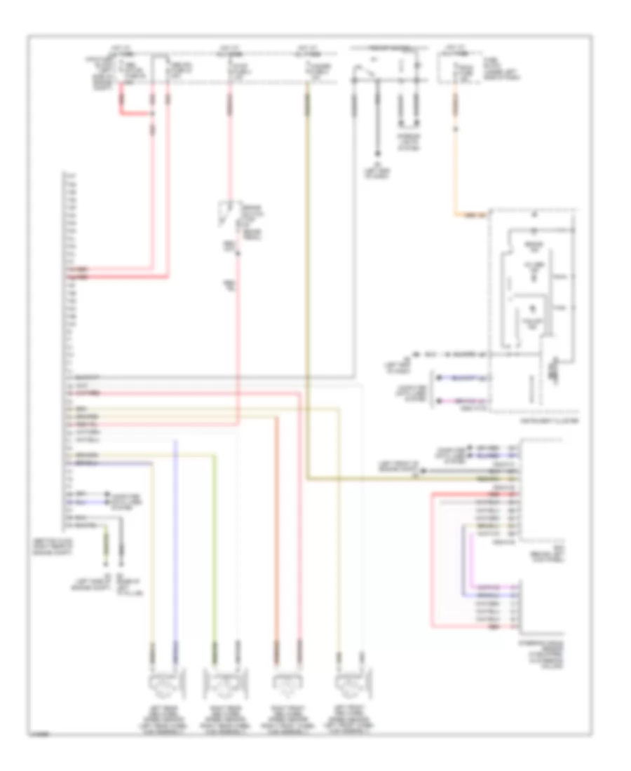
Anti-lock Brakes Wiring Diagram, with Dynamic Stability Control for Mazda 6 i SV 2009

List of elements for Anti-lock Brakes Wiring Diagram, with Dynamic Stability Control for Mazda 6 i SV 2009:
- (base of left "a" pillar)
- (left front of engine compt) g2
- (under center console) combined sensor
- 0922-101b
- 0940-01b
- 0940-01c
- 0940-01e
- 4w abs ind
- Abs motor fuse 36 60a
- Abs sol fuse 44 30a
- Bcm (behind left kick panel)
- Brake ind
- Brake switch (top of brake pedal)
- Computer data lines system
- Dsc hu/cm (right rear of engine compt)
- Dsc ind
- Dsc off ind
- Dsc off switch
- Fuse block (under left side of dash)
- G17 (under driver's seat)
- G5 g3 (left side of engine compt)
- G8 (left end of dash)
- Hazard fuse 2 10a
- Hot at all times
- Instrument cluster
- Interior lights system
- Left front abs wheel speed sensor (left front wheel hub assembly)
- Left rear abs wheel speed sensor (left rear wheel hub assembly)
- Main fuse block (left side of engine compt)
- Micro- computer
- Power distribution system
- Red
- Right front abs wheel speed sensor (right front wheel hub assembly)
- Right rear abs wheel speed sensor (right rear wheel hub assembly)
- Room fuse 15a
- Steering angle sensor (if equipped) (in steering column)
- Stop fuse 4 10a
Anti-lock Brakes Wiring Diagram, without Dynamic Stability Control for Mazda 6 i SV 2009
List of elements for Anti-lock Brakes Wiring Diagram, without Dynamic Stability Control for Mazda 6 i SV 2009:
- (base of left "a" pillar)
- (left front of engine compt) g2
- 0922-101b
- 0940-01b
- 0940-01c
- 0940-01e
- 4w abs ind
- Abs motor fuse 36 60a
- Abs sol fuse 44 30a
- Abs/tcs hu/cm (right rear of engine compt)
- Bcm (behind left kick panel)
- Brake ind
- Brake switch (top of brake pedal)
- Computer data lines system
- Fuse block (under left side of dash)
- G5 g3 (left side of engine compt)
- G8 (left end of dash)
- Hazard fuse 2 10a
- Hot at all times
- Instrument cluster
- Interior lights system
- Left front abs wheel speed sensor (left front wheel hub assembly)
- Left rear abs wheel speed sensor (left rear wheel hub assembly)
- Main fuse block (left side of engine compt)
- Micro- computer
- Red
- Right front abs wheel speed sensor (right front wheel hub assembly)
- Right rear abs wheel speed sensor (right rear wheel hub assembly)
- Room fuse 15a
- Steering angle sensor (if equipped) (in steering column)
- Stop fuse 4 10a
- Tcs off ind
- Tcs off switch