ANTI-LOCK BRAKES
Anti-lock Brakes Wiring Diagram for Mazda 6 s 2005
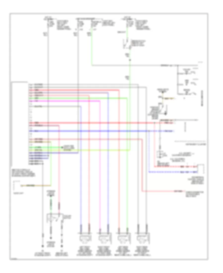
List of elements for Anti-lock Brakes Wiring Diagram for Mazda 6 s 2005:
- (at right front of engine compt)
- (behind left side of dash)
- 2.3l: california emission, 3.0l
- 2.3l: except california emission
- Abs fuse 60a
- Abs ind
- Abs/tcs hydraulic unit/control module (at right front corner of engine compartment)
- Audio unit
- Brake ind
- Brake switch (behind left
- Check connector (in main fuse & relay box)
- Computer data lines system
- G2 (behind left end of dash)
- Headlights system
- Hot at all times
- Hot in on or start
- Ill
- Instrument cluster
- Interior lights system
- J-01
- J-02
- Jc g-02
- Joint box (behind left kick panel)
- Left front abs wheel speed sensor (at left side of engine compt)
- Left rear abs wheel speed sensor (at left rear wheelwell)
- Main fuse & relay box (on left front inner fender panel)
- Meter ig fuse 15a
- Micro-computer
- Parking brake switch (at base of parking brake lever)
- Powertrain control module (behind left side of dash)
- Red
- Right front abs wheel speed sensor (at right side of engine compt)
- Right rear abs wheel speed sensor (at right rear wheelwell)
- Sas fuse 15a
- Side of dash)
- Stop fuse 15a
- Tcs off ind
- Tcs off switch
 English