ANTI-LOCK BRAKES
Anti-lock Brakes Wiring Diagram, with Dynamic Stability Control for Mazda 6 s Sport 2008

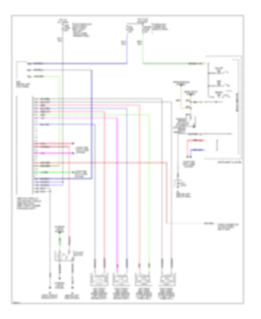
List of elements for Anti-lock Brakes Wiring Diagram, with Dynamic Stability Control for Mazda 6 s Sport 2008:
- (right side of engine compt) g3
- Abs fuse 60a
- Bcm (behind left kick panel)
- Check connector (in main fuse & relay box)
- Combined sensor (under center console)
- Computer data lines system
- Dsc hydraulic unit/control module (dsc hu/cm) (right front corner of engine compt)
- Dsc ind
- Dsc off ind
- Dsc off switch
- Exterior lights system
- Fuse block (under left side of dash)
- G2 (behind left end of dash)
- G2 (behind left end of dash) jc g-02
- G6 (behind left side of dash)
- Hot at all times
- Hot in on or start
- Ill
- Instrument cluster
- Interior lights system
- Jc g-02
- Left front abs wheel speed sensor (left side of engine compt)
- Left rear abs wheel speed sensor (at left rear wheelwell)
- Main fuse block (main fuse & relay box) (on left front inner fender panel)
- Meter fuse 15a
- Micro-computer
- Nca
- Pnk
- Red
- Right front abs wheel speed sensor (right side of engine compt)
- Right rear abs wheel speed sensor (at right rear wheelwell)
- Sas fuse 10a
- Steering angle sensor (in steering column)
Anti-lock Brakes Wiring Diagram, without Dynamic Stability Control for Mazda 6 s Sport 2008
List of elements for Anti-lock Brakes Wiring Diagram, without Dynamic Stability Control for Mazda 6 s Sport 2008:
- Abs fuse 60a
- Abs ind
- Abs/tcs hydraulic unit/control module (abs/tcs hu/cm) (right front corner of engine compt)
- Bcm (behind left kick panel)
- Brake ind
- Check connector (in main fuse & relay box)
- Computer data lines system
- Fuse block (under left side of dash)
- G2 (behind left end of dash)
- G3 (right side of engine compt)
- G6 (behind left side of dash)
- Headlights system
- Hot at all times
- Hot in on or start
- Ill
- Instrument cluster
- Interior lights system
- Jc g-02
- Left front abs wheel speed sensor (left side of engine compt)
- Left rear abs wheel speed sensor (at left rear wheelwell)
- Main fuse block (main fuse & relay box) (on left front inner fender panel)
- Meter fuse 15a
- Micro-computer
- Parking brake switch (at base of parking brake assembly)
- Pnk
- Red
- Right front abs wheel speed sensor (right side of engine compt)
- Right rear abs wheel speed sensor (at right rear wheelwell)
- Sas fuse 10a
- Tcs off ind
- Tcs off switch
- Transmissions system