ANTI-LOCK BRAKES
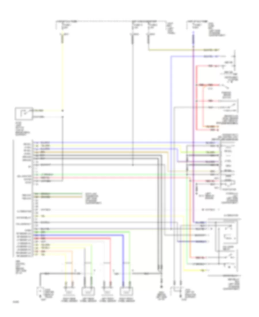
Anti-lock Brake Wiring Diagrams for Mazda 626 DX 1994
List of elements for Anti-lock Brake Wiring Diagrams for Mazda 626 DX 1994:
- (canada only) drl control unit (behind left side of i/p)
- (left kick panel)
- (left rear of engine)
- (left side of engine compartment)
- (top of brake pedal support)
- 2b
- Abs control unit (behind left side of i/p)
- Abs ind
- Abs relay box (left side of engine compartment)
- Alternator
- Brake fluid level sensor (left rear of eng compartment)
- Brk ind
- Data link connector (left side of engine compartment)
- Fail-safe relay
- Fail-safe rly
- Fbs chk
- Fuse 1 20a
- Fuse 10 15a
- Fuse 7 60a
- Fuse 8 15a
- G108
- G114
- G202 (behind left side of i/p)
- G407
- Ground
- Hot at all times
- Hot at all times main fuse box
- Hot in run and start
- Hydraulic unit (left side of engine compartment)
- Ind
- Instrument cluster
- Jc-01 (left of radiator support)
- Jc-05 (center rear of trunk)
- Joint box
- Left front wheel sensor
- Left rear wheel sensor
- Lf sensr (hi)
- Lf sensr (lo)
- Lf sol
- Lr sensr (hi)
- Lr sensr (lo)
- Lr sol
- Motor
- Motor relay
- Nca
- O-03
- O-04
- Parking brake switch
- Pump motor
- Red
- Rf sensr (hi)
- Rf sensr (lo)
- Rf sol
- Right front wheel sensor
- Right rear wheel sensor
- Rr sensr (hi)
- Rr sensr (lo)
- Rr sol
- Sol monitor
- Stop
- Stop lamp switch
- Tbs chk
- Warn
- X-13
 English