ANTI-LOCK BRAKES
Anti-lock Brake Wiring Diagrams for Mazda 626 ES 1995
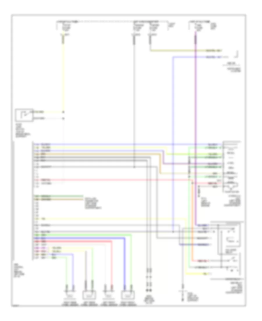
List of elements for Anti-lock Brake Wiring Diagrams for Mazda 626 ES 1995:
- (top of brake pedal support)
- 2b
- Abs control unit (behind left side of i/p)
- Abs fuse 60a
- Abs ind
- Abs relay box (left side of engine compartment)
- Data link connector (left side of engine compartment)
- Engine fuse 15a
- Fail-safe relay
- G108 (left of radiator support)
- G114 (left rear of engine)
- G202 (behind left side of i/p)
- Hot at all times
- Hot at all times main fuse box
- Hot in run and start
- Hydraulic unit (left side of engine compartment)
- Instrument cluster
- Joint box
- Left front wheel sensor
- Left rear wheel sensor
- Lf sol
- Lr sol
- Meter fuse 15a
- Motor relay
- Nca
- O-03
- Pnk
- Pump motor
- Red
- Rf sol
- Right front wheel sensor
- Right rear wheel sensor
- Rr sol
- Stop fuse 20a
- Stop lamp switch
 English