ANTI-LOCK BRAKES
Anti-lock Brake Wiring Diagrams for Mazda 626 LX 1999
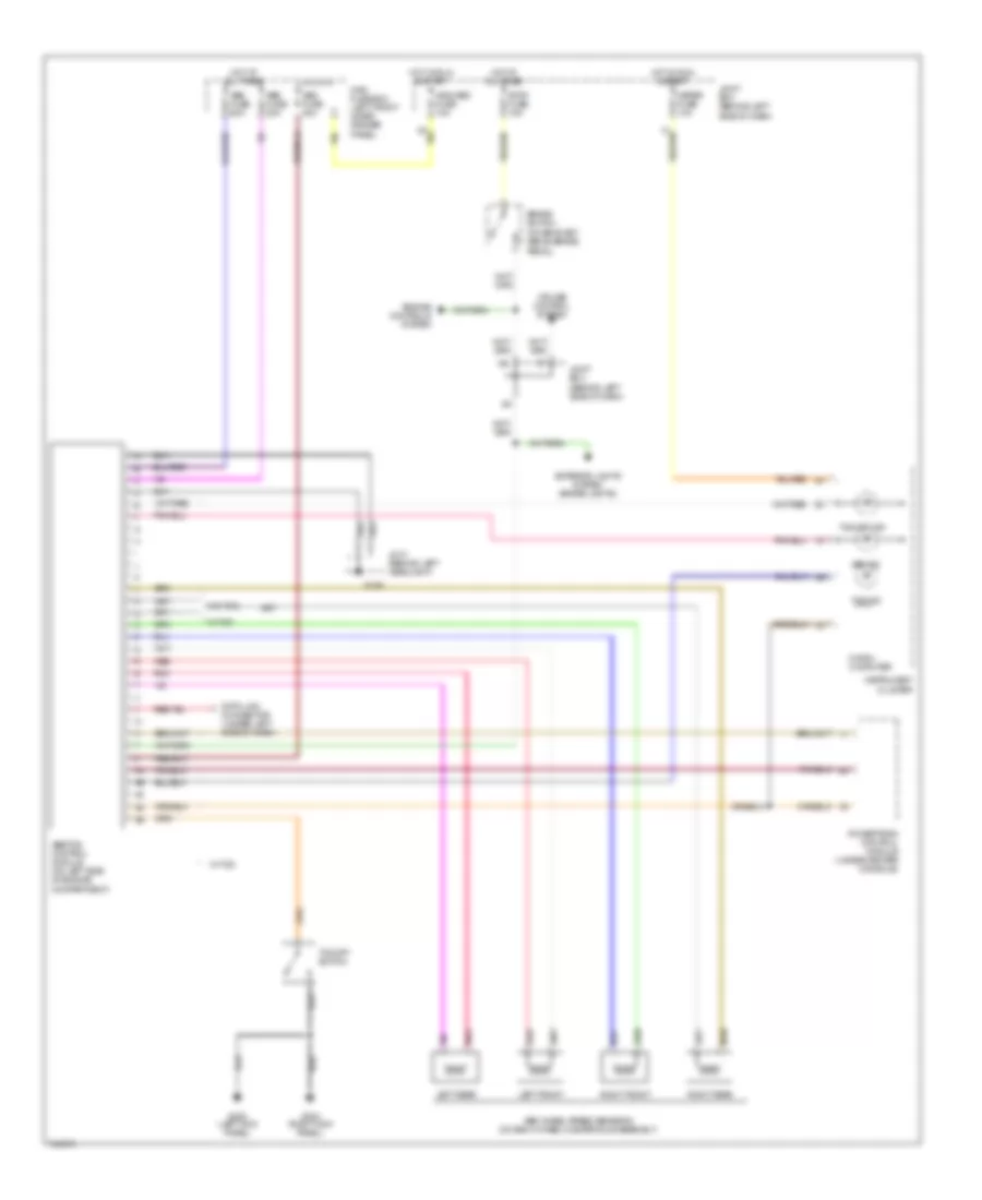
List of elements for Anti-lock Brake Wiring Diagrams for Mazda 626 LX 1999:
- (on bracket, above brake pedal)
- 10l
- A/b & abs fuse 10a
- Abs fuse 20a
- Abs fuse 60a
- Abs ind
- Abs wheel speed sensors (on each wheel hub/spindle assembly)
- Abs/tcs control module (on left side of engine compartment)
- Brake switch
- Cruise control system
- Data link connector (under left side of dash)
- Engine controls system
- Exterior lights system (brake lights)
- G106
- G200 (left kick panel)
- G203 (right kick panel)
- Hot at all times
- Hot in run & start
- Instrument cluster
- Jc-01 (behind left headlight)
- Joint box (behind left side of dash)
- Left front
- Left rear
- Main fuse box (left front inner fender panel)
- Meter fuse 10a
- Micro- computer
- Pnk
- Powertrain control module (under center console)
- Red
- Right front
- Right rear
- Stop fuse 15a
- Tcs ind
- Tcs off ind
- Tcs off switch
- W/ tcs
- W/o tcs
 Русский