ANTI-LOCK BRAKES
Anti-lock Brakes Wiring Diagram for Mazda B3000 2006
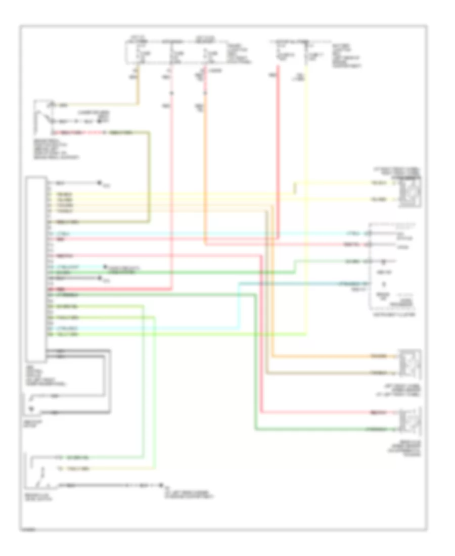
List of elements for Anti-lock Brakes Wiring Diagram for Mazda B3000 2006:
- (at right front wheel) right front wheel speed sensor
- (under driver's seat) g10
- 0922-101
- 4x4 status
- Abs control module (on left front inner fender panel)
- Abs ind
- Abs pump motor
- Battery junction box (left rear of engine compartment)
- Brake fluid level switch
- Brake ind
- Brake pedal position switch (behind left side of dash, on brake pedal support)
- Computer data lines system
- Fuse 10a
- Fuse 17 40a
- Fuse 33 30a
- Fuse 5a
- G12
- G3 (at left rear corner of engine compartment)
- Hot at all times
- Hot in on or start
- Hot in run
- Instrument cluster
- J-2280b
- Left front wheel speed sensor (at left front wheel)
- Micro- processor
- Nca
- Rear axle speed sensor (on differential housing)
- Red
- Red red
- Red/pnk
- Smart junction box (at right kick panel)
- Vpwr
 English