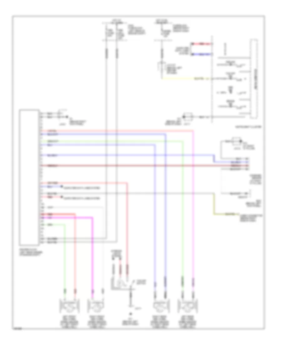
ANTI-LOCK BRAKES
Anti-lock Brakes Wiring Diagram for Mazda CX-9 Touring 2008
List of elements for Anti-lock Brakes Wiring Diagram for Mazda CX-9 Touring 2008:
- (behind left side of dash)
- 0940-01f
- Abs (sol) fuse 30a
- Abs fuse 50a
- Abs ind
- Bcm (behind left kick panel)
- Brake ind
- Check connector (behind right side of dash)
- Combined sensor (at right "c" pillar)
- Computer data lines system
- Dsc ind
- Dsc/rsc hu/cm (left rear corner of engine compt)
- Fuse block (behind right side of dash)
- G1 (behind right kick panel)
- G11
- G11 (behind left side of dash) j/c-11
- G12 (at right "c" pillar)
- Hot at all times
- Hot in on or start
- Ill
- Instrument cluster
- Interior lights system
- J/c c-37 (behind left center of dash)
- J/c-01
- J/c-11
- J/c-12
- Left front abs wheel speed sensor (at left front wheelwell)
- Left rear abs wheel speed sensor (at left rear wheelwell)
- Main fuse block (left rear of engine compt)
- Meter fuse 10a
- Micro computer
- Nca
- Red
- Right front abs wheel speed sensor (at right front wheelwell)
- Right rear abs wheel speed sensor (at right rear wheelwell)
- Tcs off ind
- Tcs off switch
 English