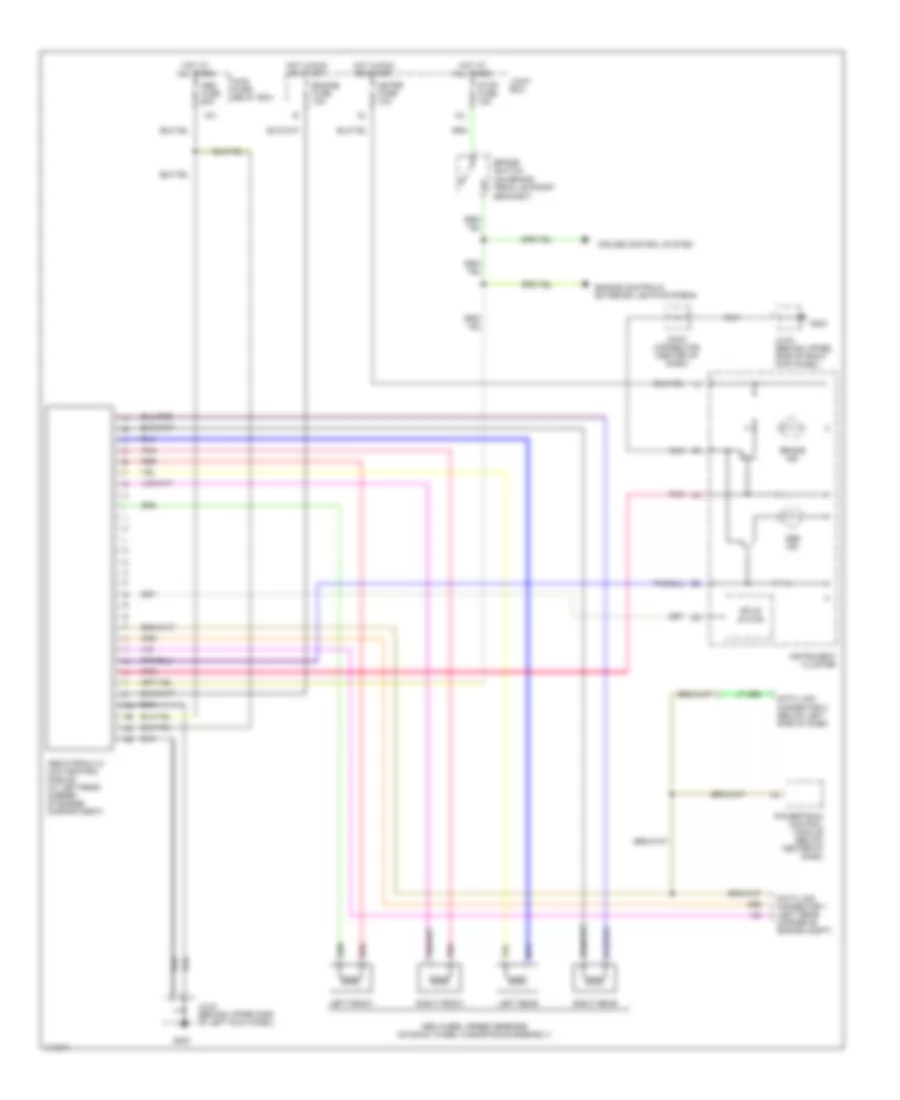
ANTI-LOCK BRAKES
Anti-lock Brake Wiring Diagrams for Mazda MPV ES 2001
List of elements for Anti-lock Brake Wiring Diagrams for Mazda MPV ES 2001:
- (on brake pedal support bracket)
- 10l
- Abs fuse 60a
- Abs hydraulic unit/control module (at left rear corner of engine compartment)
- Abs ind
- Abs wheel speed sensors (on each wheel hub/spindle assembly)
- Brake ind
- Brake switch
- Cruise control system
- Data link connector 1 (left rear corner of engine compt)
- Data link connector 2 (below left side of dash)
- Engine controls, exterior lights systems
- Engine fuse 10a
- G200
- G203
- Hot at all times
- Hot in run or start
- Instrument cluster
- Jc-03 (behind upper side of right kick panel)
- Jc-04 (behind upper side of left kick panel)
- Joint box
- Joint connector (center of dash)
- Left front
- Left rear
- Main fuse/ relay box
- Meter fuse 10a
- Pnk
- Powertrain control module (below center of dash)
- Red
- Right front
- Right rear
- Solid state
- Stop fuse 15a
- X01
 English