ANTI-LOCK BRAKES
Anti-lock Brake Wiring Diagrams for Mazda MX-3 1995
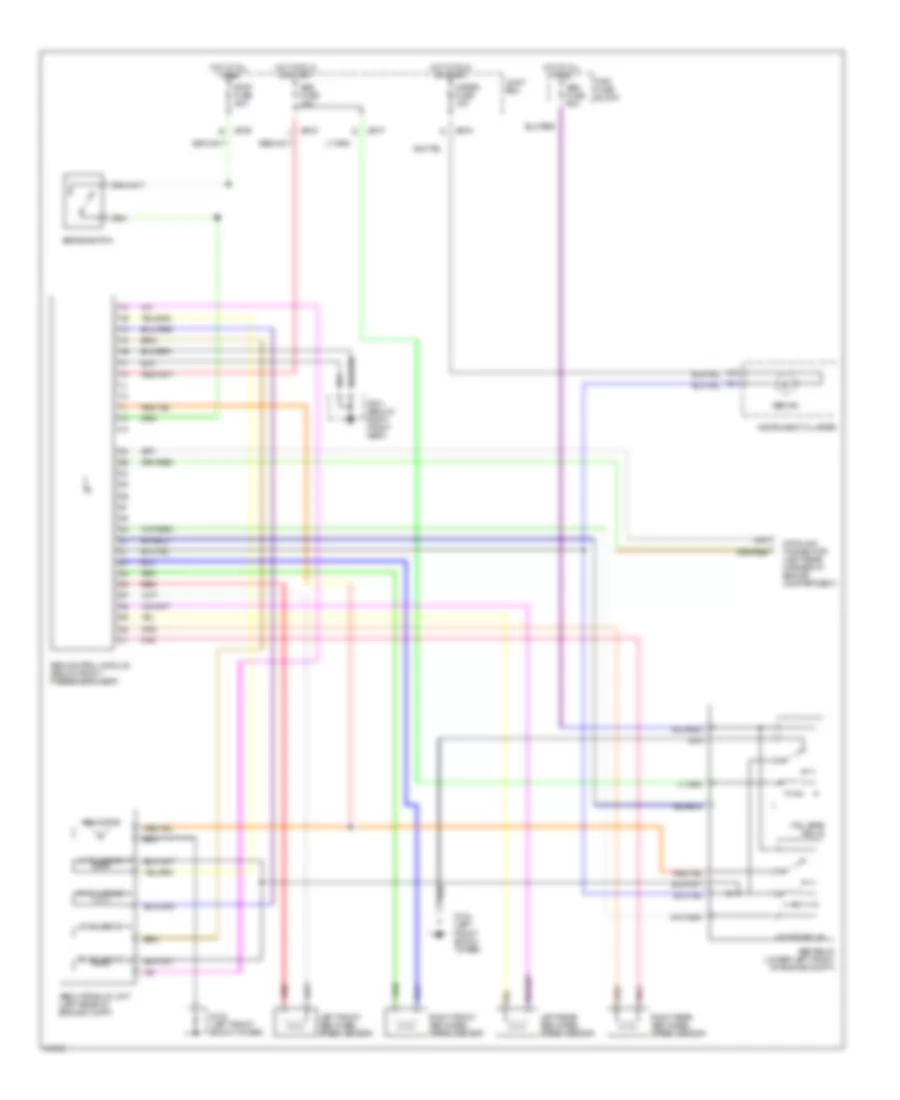
List of elements for Anti-lock Brake Wiring Diagrams for Mazda MX-3 1995:
- Abs control module (below front passenger's seat)
- Abs fuse 10a
- Abs fuse 60a
- Abs hydraulic unit (left rear of engine compt)
- Abs ind
- Abs motor
- Abs relay (lower left front of engine compt)
- Brake switch
- Data link connector (left rear corner of engine compartment)
- Fail-safe relay
- G104 (left front shock tower)
- G301 (below right front seat)
- Hot at all times
- Hot at run or start
- Instrument cluster
- Jb-03
- Jb-04
- Jb-05
- Jb-07
- Joint box
- Left front abs wheel speed sensor
- Left rear abs wheel speed sensor
- Lf solenoid
- Lr solenoid
- Main fuse block
- Meter fuse 15a
- Motor relay
- Pnk
- Red
- Rf solenoid
- Right front abs wheel speed sensor
- Right rear abs wheel speed sensor
- Rr solenoid
- Stop fuse 20a
 English