ANTI-LOCK BRAKES
Anti-lock Brakes Wiring Diagram for Mazda MX-5 Miata 2005
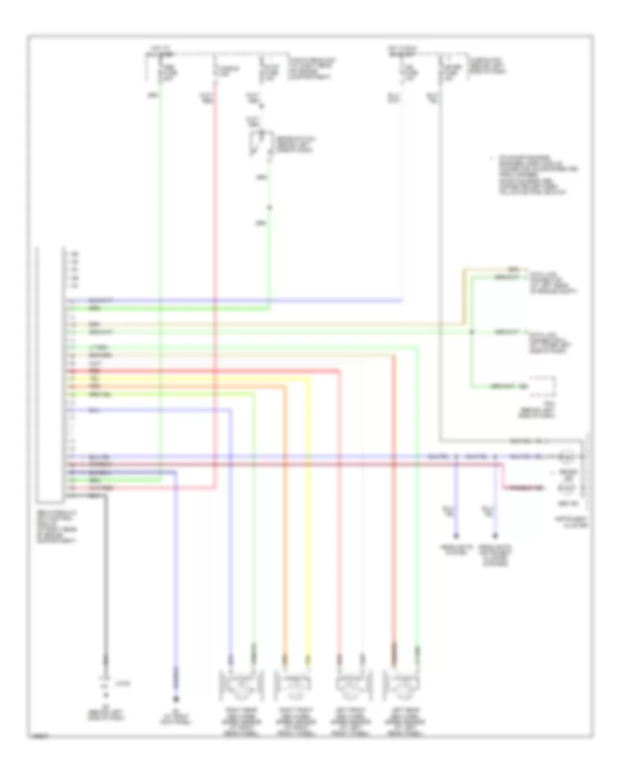
List of elements for Anti-lock Brakes Wiring Diagram for Mazda MX-5 Miata 2005:
- A/b fuse 10a
- Abs fuse 20a
- Abs hydraulic unit/control module (at right rear of engine compartment)
- Abs ind
- Brake ind
- Brake switch (behind left side of dash)
- Data link connector (at left rear of engine compt)
- Data link connector 2 (at lower left side of dash)
- Fuse block (behind left side of dash)
- Fusible link
- G2 (behind left side of dash)
- G4 (at right kick panel)
- Headlights system
- Headlights, instrument cluster systems
- Hot at all times
- Hot in run or start
- Instrument cluster
- J/c-02
- Left front abs wheel speed sensor (at left front wheel)
- Left rear abs wheel speed sensor (at left rear wheel)
- Main fuse block (at right rear of engine compartment)
- Meter fuse 15a
- Pcm (behind left side of dash)
- Pin shorting bars engaged when module connector is disconnected from harness. shorting bars are connected between following pins: e-d & d-f
- Red
- Right front abs wheel speed sensor (at right front wheel)
- Right rear abs wheel speed sensor (at right rear wheel)
- Stop fuse 15a
 Русский