ANTI-LOCK BRAKES
Anti-lock Brake Wiring Diagrams for Mazda Protege ES 1997
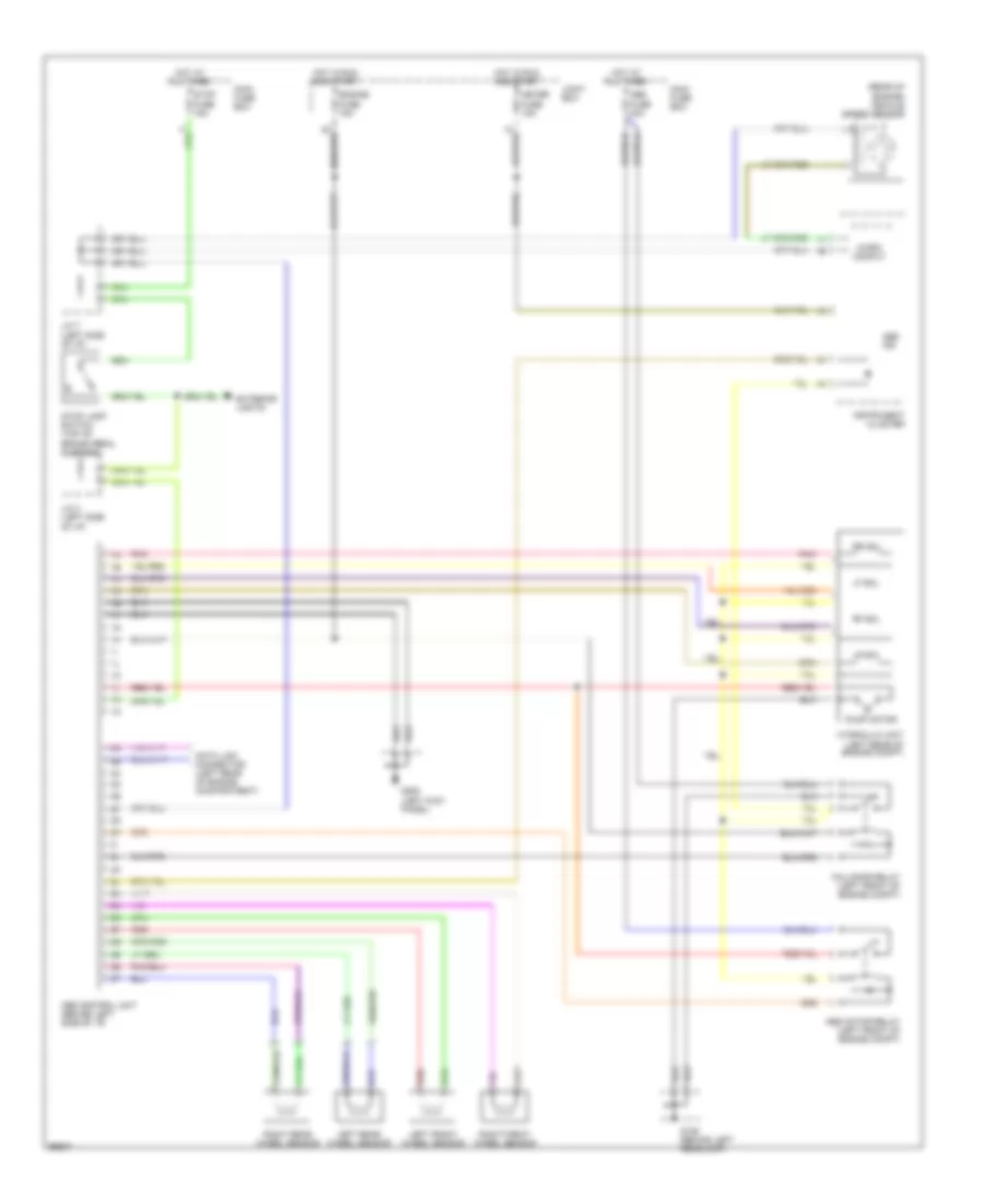
List of elements for Anti-lock Brake Wiring Diagrams for Mazda Protege ES 1997:
- (rear of engine) vehicle speed sensor
- 2b
- Abs control unit (behind left side of i/p)
- Abs fuse 40a
- Abs ind
- Abs motor relay (left front of engine compt)
- Brake pedal support)
- Data link connector (left rear of engine compartment)
- Engine fuse 15a
- Exterior lights
- Fail-safe relay (left front of engine compt)
- G106 (behind left headlamp)
- G200 (left kick panel)
- Hot at all times
- Hot in run and start
- Hydraulic unit (left rear of engine compt)
- Instrument cluster
- J/c 3 (left side
- J/c 7 (left side
- Joint box
- Left front wheel sensor
- Left rear wheel sensor
- Lf sol
- Lr sol
- Main fuse box
- Meter fuse 15a
- Micro comput
- Of i/p)
- Pnk
- Pump motor
- Red
- Rf sol
- Right front wheel sensor
- Right rear wheel sensor
- Rr sol
- Stop fuse 15a
- Stop lamp switch (top of
 English