ANTI-LOCK BRAKES
Anti-lock Brake Wiring Diagrams for Mazda Protege LX 1998
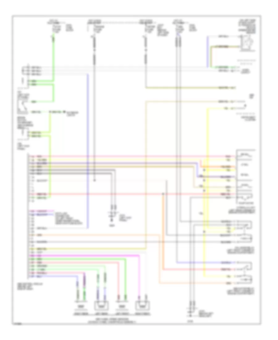
List of elements for Anti-lock Brake Wiring Diagrams for Mazda Protege LX 1998:
- (on left side of eng compt, in transaxle) vehicle speedometer sensor
- 2b
- Above brake pedal)
- Abs control module (behind left side of dash)
- Abs fuse 40a
- Abs ind
- Abs motor relay (left front corner of engine compartment)
- Abs wheel speed sensors (on each wheel hub/spindle assembly)
- Brake switch (on bracket,
- Data link connector (on left front inner fender panel, near main fuse block)
- Engine fuse 15a
- Exterior lights
- Fail-safe relay (left front corner of engine compartment)
- G106
- G200
- Hot at all times
- Hot in run and start
- Hydraulic unit (left rear corner of engine compartment)
- Instrument cluster
- Jc-01 (left kick panel)
- Jc-03 (behind left headlight)
- Joint box (behind left side of dash)
- Left front
- Left rear
- Lf sol
- Lr sol
- Main fuse block
- Meter fuse 15a
- Micro comput
- Of panel)
- Panel)
- Pnk
- Pump motor
- Red
- Rf sol
- Right front
- Right rear
- Rr sol
- Stop fuse 15a
- X25 (left kick
- X27 (left kick
 English