ANTI-LOCK BRAKES
Anti-lock Brakes Wiring Diagram for Mazda Tribute i 2005
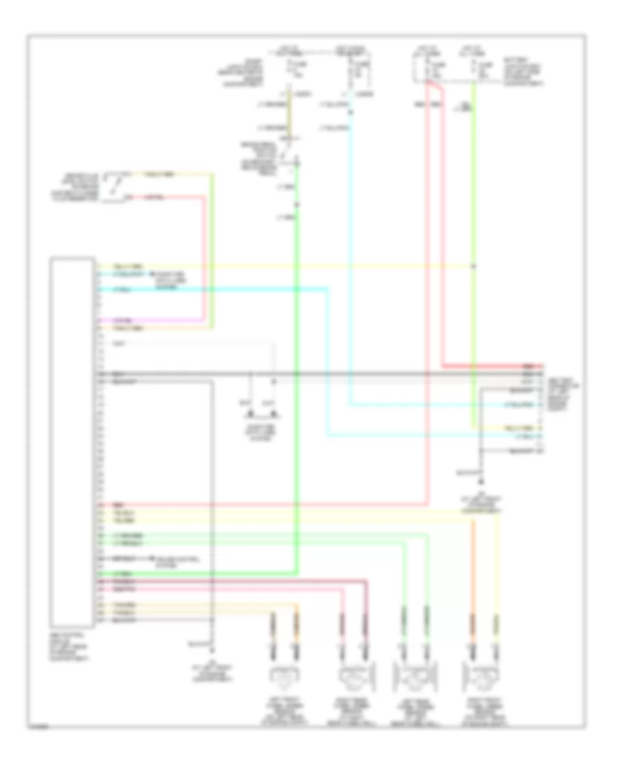
List of elements for Anti-lock Brakes Wiring Diagram for Mazda Tribute i 2005:
- Abs control module (at left rear of engine compartment)
- Abs test connector (at left rear of engine compt)
- Battery junction box (on left side of engine compartment)
- Brake fluid level switch (on brake master cylinder fluid reservoir)
- Brake pedal position switch (on bracket, above brake pedal)
- Computer data lines
- Computer data lines system
- Cruise control system
- Fuse 15a
- Fuse 30a
- Fuse 5a
- Fuse 60a
- G4 (at left front of engine compartment)
- Hot at all times
- Hot in run or start
- J-2280b
- J-2280c
- Left front wheel speed sensor (on left rear of engine compt)
- Left rear wheel speed sensor (at left rear wheelwell)
- Nca
- Red
- Red/pnk
- Right front wheel speed sensor (on right rear of engine compt)
- Right rear wheel speed sensor (at right rear wheelwell)
- Smart junction box (rear center of engine compartment)
- System
 Русский