ANTI-LOCK BRAKES
Anti-lock Brakes Wiring Diagram, Except Hybrid for Mazda Tribute i Grand Touring 2010

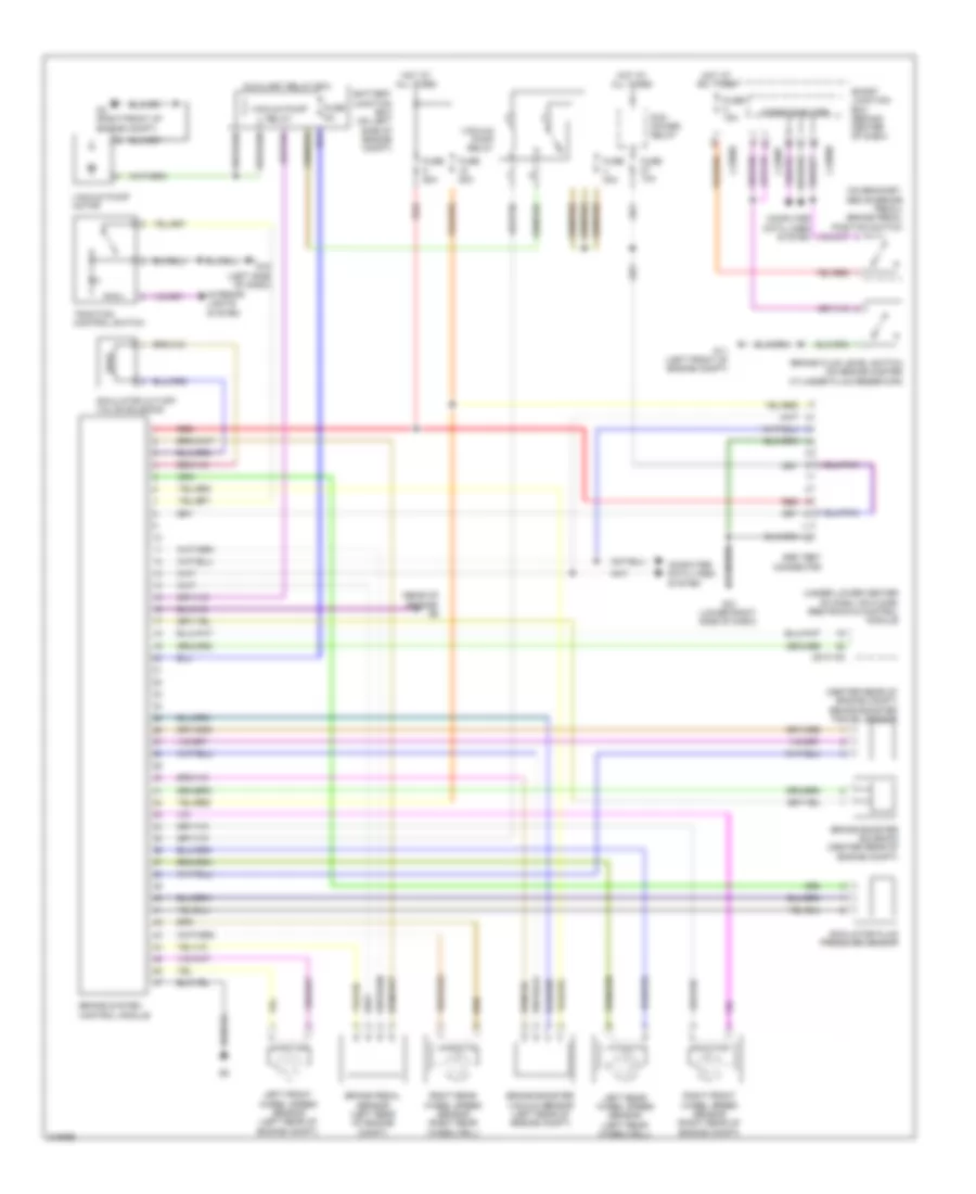
List of elements for Anti-lock Brakes Wiring Diagram, Except Hybrid for Mazda Tribute i Grand Touring 2010:
- 0810-102
- Abs control module (left rear of engine compt)
- Abs test connector
- Battery junction box (on left side of engine compt)
- Brake fluid level switch (left rear of engine compt)
- Brake pedal position switch (on bracket, above brake pedal)
- Computer data lines system
- Fuse 15a
- Fuse 20a
- Fuse 50a
- Fuse 5a
- G11 (left front of engine compt)
- G14 (lower left side of dash)
- G5 (left front of engine compt)
- Hot at all times
- Hot in run or start
- J-2280b
- J-2280d
- J-2280f
- Left front wheel speed sensor (left rear of engine compt)
- Left rear wheel speed sensor (left rear wheelwell)
- Microcomputer
- Red
- Restraints control module
- Right front wheel speed sensor (right rear of engine compt)
- Right rear wheel speed sensor (right rear wheelwell)
- Smart junction box (behind center of dash)
- Traction assist disable switch
Anti-lock Brakes Wiring Diagram, Hybrid for Mazda Tribute i Grand Touring 2010
List of elements for Anti-lock Brakes Wiring Diagram, Hybrid for Mazda Tribute i Grand Touring 2010:
- (center rear of engine compt) brake booster travel sensor
- (on bracket, above brake pedal) brake pedal position switch
- (rear of engine) g9
- (under lower center of dash, on floor) restraints control module
- 0810-102
- Abs test connector
- Auxiliary relay box
- Battery junction box (on left side of engine compt)
- Brake booster solenoid (center rear of engine compt)
- Brake booster vacuum sensor (left rear of engine compt)
- Brake fluid level switch (on brake master cylinder fluid reservoir)
- Brake pedal sensor (left rear of engine compt)
- Brake system control module
- Computer data lines system
- Fuse 10a
- Fuse 15a
- Fuse 40a
- Fuse 50a
- Fuse 5a
- G11 (left front of engine compt)
- G12 (lower right side of dash)
- G15 (left side of dash)
- G3 (right front of engine compt)
- Hot at all times
- Interior lights system
- J-2280b
- J-2280d
- J-2280f
- Left front wheel speed sensor (left rear of engine compt)
- Left rear wheel speed sensor (left rear wheelwell)
- Microcomputer
- Pcm power relay
- Red
- Right front wheel speed sensor (right rear of engine compt)
- Right rear wheel speed sensor (right rear wheelwell)
- Simulator cut-off valve solenoid
- Simulator fluid pressure sensor
- Smart junction box (behind center of dash)
- Traction control switch
- Vacuum pump motor
- Vacuum pump relay