ANTI-LOCK BRAKES
Anti-Lock Brakes Wiring Diagram for Mercedes-Benz 500SEL 1993

List of elements for Anti-Lock Brakes Wiring Diagram for Mercedes-Benz 500SEL 1993:
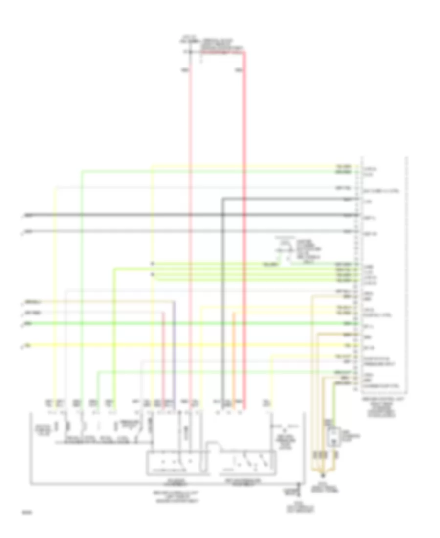
Traction Control Wiring Diagram (1 of 2) for Mercedes-Benz 500SEL 1993
List of elements for Traction Control Wiring Diagram (1 of 2) for Mercedes-Benz 500SEL 1993:
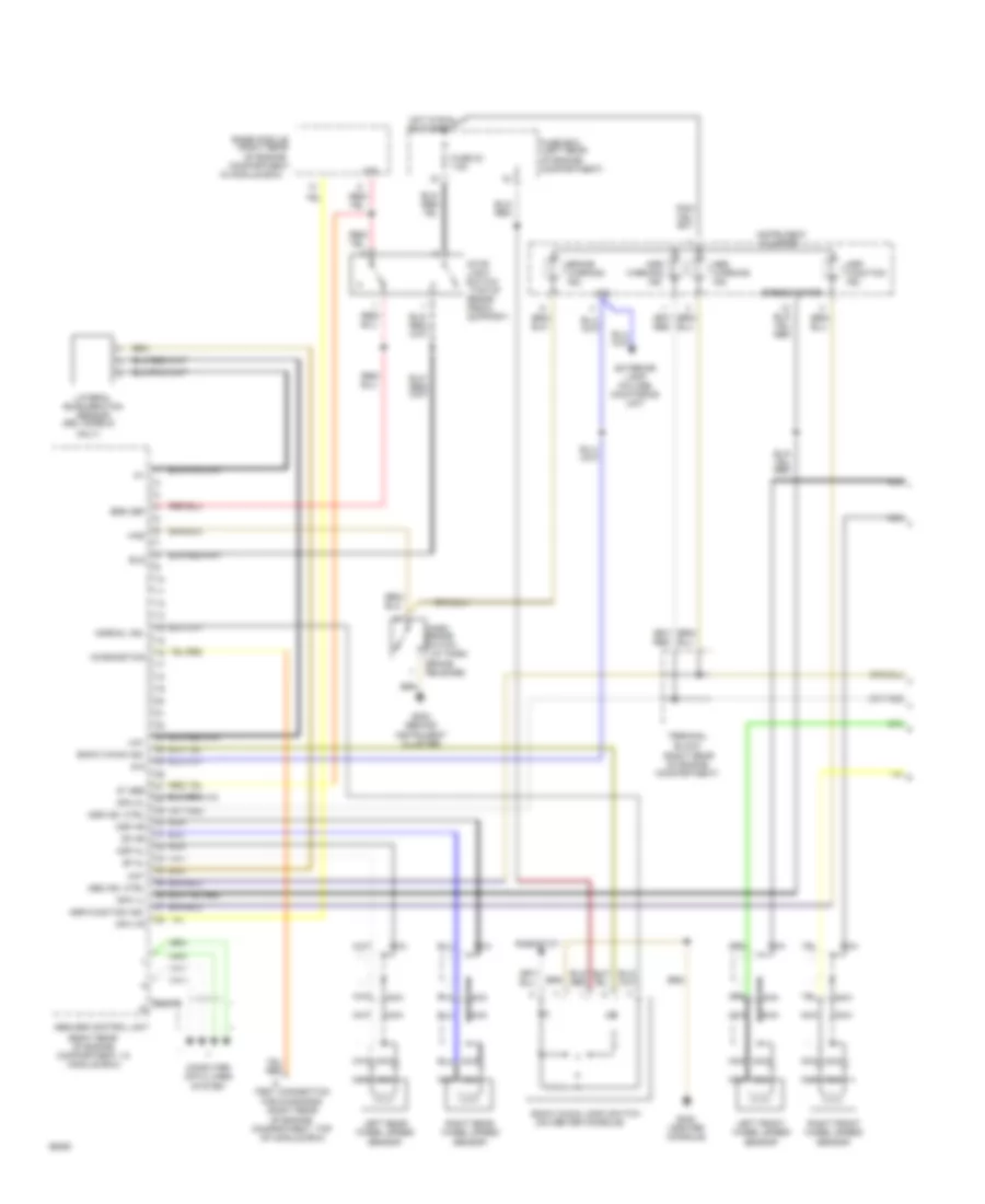
Traction Control Wiring Diagram (2 of 2) for Mercedes-Benz 500SEL 1993
List of elements for Traction Control Wiring Diagram (2 of 2) for Mercedes-Benz 500SEL 1993: