ANTI-LOCK BRAKES
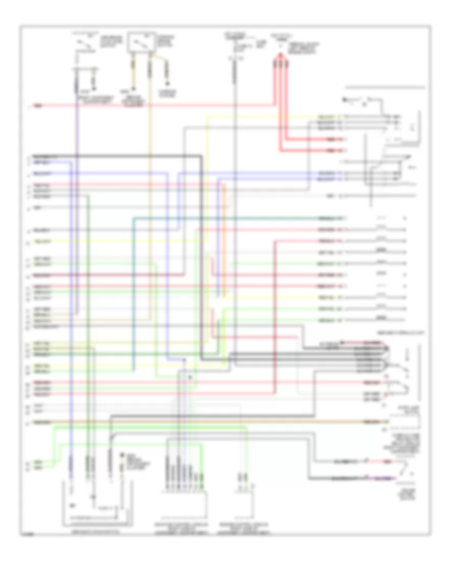
Anti-lock Brake Wiring Diagrams, with Acceleration Slip Regulation (1 of 2) for Mercedes-Benz C220 1994

List of elements for Anti-lock Brake Wiring Diagrams, with Acceleration Slip Regulation (1 of 2) for Mercedes-Benz C220 1994:
Anti-lock Brake Wiring Diagrams, with Acceleration Slip Regulation (2 of 2) for Mercedes-Benz C220 1994
List of elements for Anti-lock Brake Wiring Diagrams, with Acceleration Slip Regulation (2 of 2) for Mercedes-Benz C220 1994:
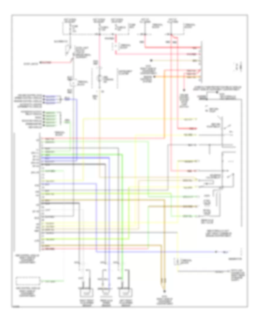
Anti-lock Brake Wiring Diagrams, without Acceleration Slip Regulation for Mercedes-Benz C220 1994
List of elements for Anti-lock Brake Wiring Diagrams, without Acceleration Slip Regulation for Mercedes-Benz C220 1994: