ANTI-LOCK BRAKES
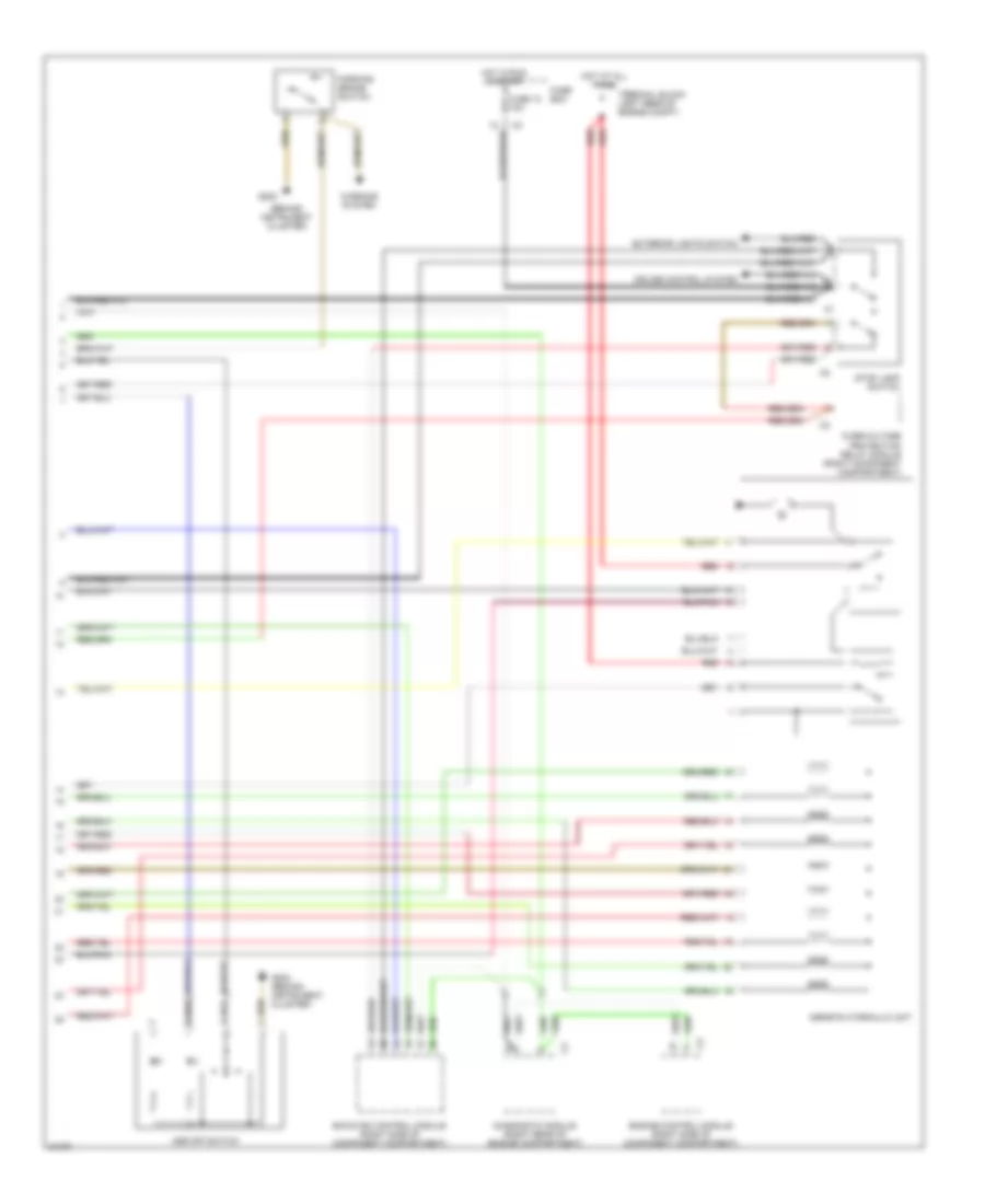
Anti-lock Brake Wiring Diagrams, with Acceleration Slip Regulation (1 of 2) for Mercedes-Benz C280 1995

List of elements for Anti-lock Brake Wiring Diagrams, with Acceleration Slip Regulation (1 of 2) for Mercedes-Benz C280 1995:
- (right rear of component compt)
- Abs ind
- Asd/ asr ind
- Asr on ind
- Asr/sps control module (right side of component compartment)
- C2b
- C2d
- Data link connector (left side of engine compt)
- Fuse 6 7.5a
- Fuse block
- G105
- G105 (right rear of component compt)
- Generator
- Hot in run or start
- Instrument cluster
- Left front axle vss speed sensor
- Left rear axle vss speed sensor
- Nca
- Pnk/ red
- Right front axle vss speed sensor
- Right rear axle vss speed sensor
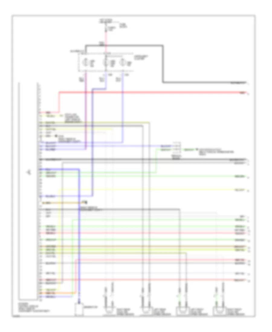
Anti-lock Brake Wiring Diagrams, with Acceleration Slip Regulation (2 of 2) for Mercedes-Benz C280 1995
List of elements for Anti-lock Brake Wiring Diagrams, with Acceleration Slip Regulation (2 of 2) for Mercedes-Benz C280 1995:
- (behind instrument cluster)
- Asr off switch
- Asr/ets hydraulic unit
- Cruise control system
- Diagnostic module (right rear of engine compartment)
- Ea/cc/isc control module (right side of component compartment)
- Engine control module (right side of component compartment)
- Exterior lights switch
- Fuse 12 10a
- Fuse box
- G202
- G202 (behind instrument cluster)
- Hot at all times
- Hot in run or start
- Overvoltage protection relay module (right component compartment)
- Parking brake switch
- Red
- Stop lamp switch
- Terminal block (left rear of engine compt)
- Warning system
Anti-lock Brake Wiring Diagrams, with Traction Control (1 of 2) for Mercedes-Benz C280 1995
List of elements for Anti-lock Brake Wiring Diagrams, with Traction Control (1 of 2) for Mercedes-Benz C280 1995:
- (right rear of component compt)
- Abs ind
- Asd/ asr ind
- Asr on ind
- C2b
- C2d
- Data link connector (left side of engine compt)
- Ets/sps control module (right side of component compartment)
- Fuse 6 7.5a
- Fuse block
- G105
- G105 (right rear of component compt)
- Generator
- Hot in run or start
- Instrument cluster
- Kick down,cutout relay module, speedometer, radio
- Left front axle vss speed sensor
- Left rear axle vss speed sensor
- Nca
- Pnk/ red
- Red
- Right front axle vss speed sensor
- Right rear axle vss speed sensor
- Terminal block
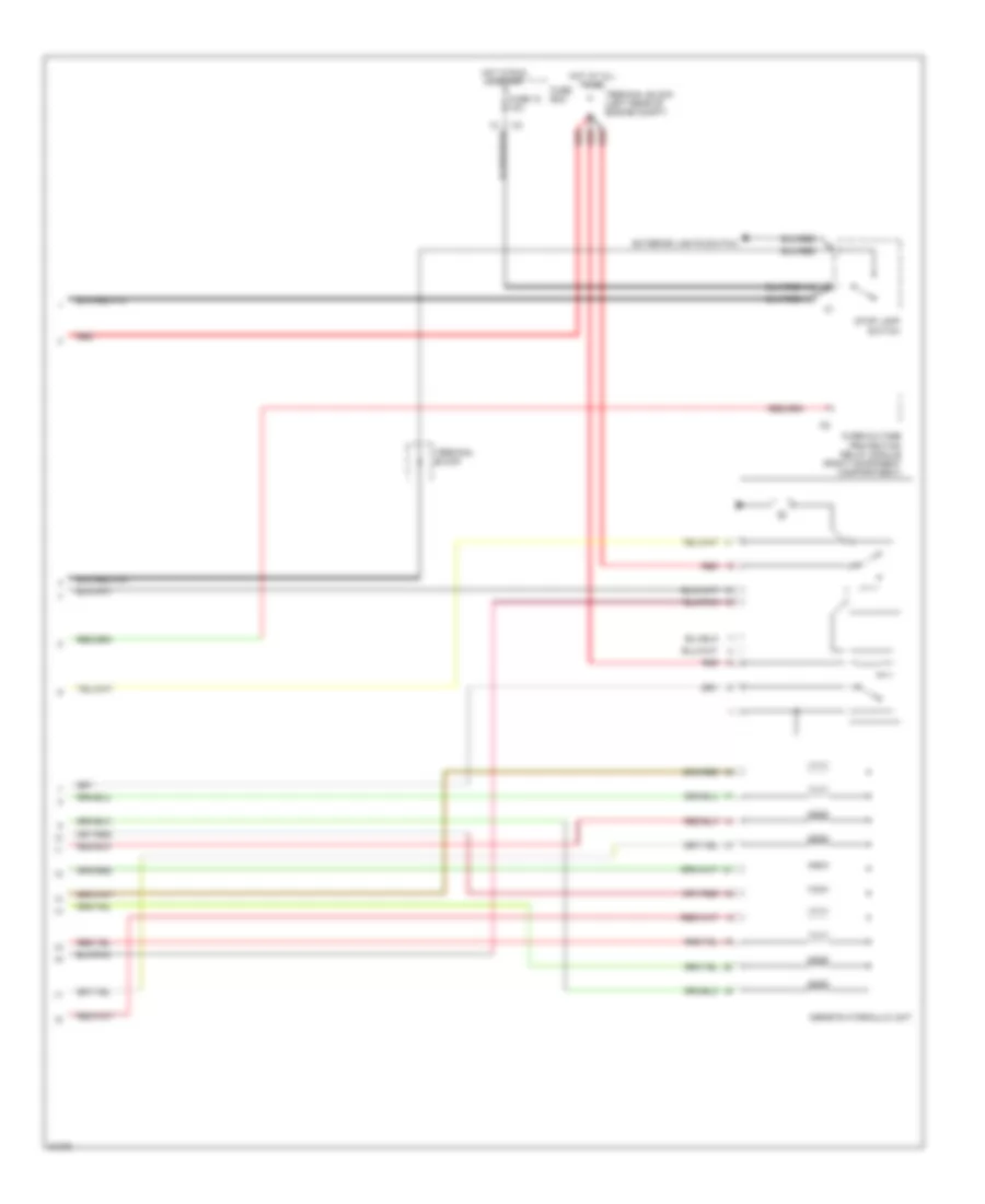
Anti-lock Brake Wiring Diagrams, with Traction Control (2 of 2) for Mercedes-Benz C280 1995
List of elements for Anti-lock Brake Wiring Diagrams, with Traction Control (2 of 2) for Mercedes-Benz C280 1995:
- Asr/ets hydraulic unit
- Exterior lights switch
- Fuse 12 10a
- Fuse box
- Hot at all times
- Hot in run or start
- Overvoltage protection relay module (right component compartment)
- Red
- Stop lamp switch
- Terminal block
- Terminal block (left rear of engine compt)