ANTI-LOCK BRAKES
Anti-lock Brakes Wiring Diagram (1 of 2) for Mercedes-Benz E320 2005

List of elements for Anti-lock Brakes Wiring Diagram (1 of 2) for Mercedes-Benz E320 2005:
- (pin 5-9 not used)
- 12v
- Dfhl a a
- Dfhr a a
- Dfvl a a
- Dfvr a a
- Driver side sam control module with fuse & relay module (left rear of eng compt)
- Front axle balance valve
- Front prefuse box (right front footwell)
- Fuse 40a
- Fuse 50a
- High pressure charging pump
- Hot at all times
- Left front outlet control valve
- Left front separation valve
- Left front wheel speed sensor (left front wheelhouse)
- Left rear inlet control valve
- Left rear outlet control valve
- Left rear wheel speed sensor (left front wheelhouse)
- Nca
- Rear axle balance valve
- Rear sam control module with fuse & relay module (left side of trunk)
- Right front inlet control valve
- Right front outlet control valve
- Right front separation valve
- Right front wheel speed sensor (left front wheelhouse)
- Right rear inlet control valve
- Right rear outlet control valve
- Right rear wheel speed sensor (left front wheelhouse)
- Sbc hydraulic unit (right front of engine compt)
- Solid state
- W3/1 (right front wheelhousing, at ignition coil)
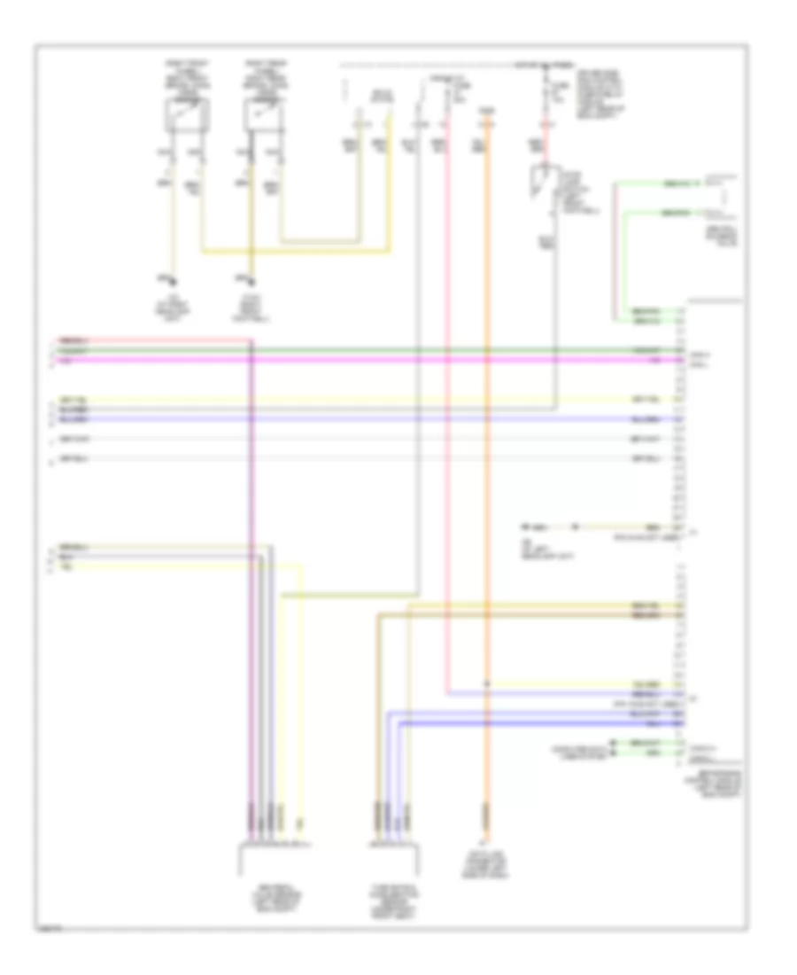
Anti-lock Brakes Wiring Diagram (2 of 2) for Mercedes-Benz E320 2005
List of elements for Anti-lock Brakes Wiring Diagram (2 of 2) for Mercedes-Benz E320 2005:
- data link connector (lower left side of dash)
- (pin 15-28 not used)
- (pin 24-48 not used)
- (right front wheel) right front brake lining wear sensor
- (right rear wheel) right rear brake lining wear sensor
- Can h
- Can l
- Can-c h
- Can-c l
- Circuit 87
- Computer data lines system
- Diag
- Driver side sam control module with fuse & relay module (left rear of eng compt)
- Esp/sps/bas control module (left rear of eng compt)
- Fuse 10a
- Fuse 20a
- Hot at all times
- I13
- Nca
- Sbc pedal value sensor (left rear of eng compt)
- Solid state
- Sps (pml) solenoid valve
- Stop lamp switch (left front footwell)
- Turn rate & acceleration sensor (under right front seat)
- W15/1 (right front footwell)
- W2 (at right headlamp unit)
- W9 (at left headlamp unit)