ANTI-LOCK BRAKES
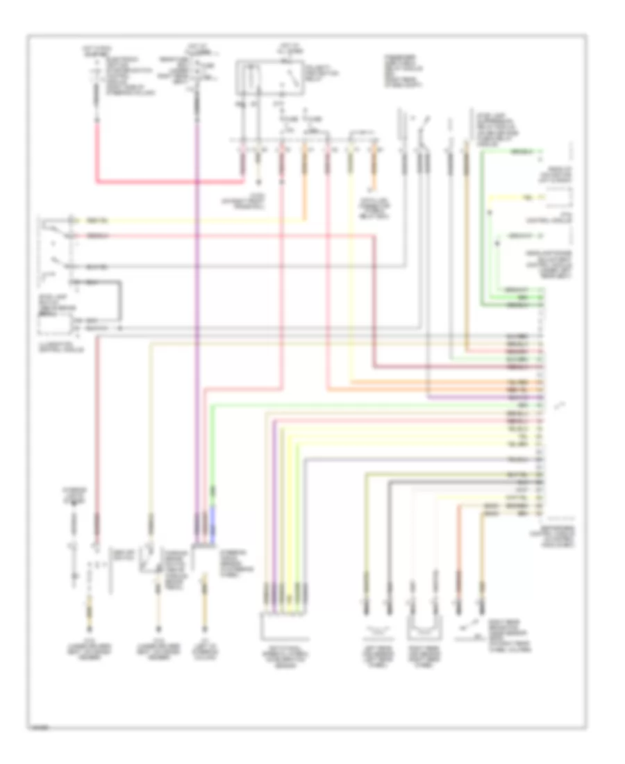
Anti-lock Brakes Wiring Diagram, Wagon (1 of 2) for Mercedes-Benz E320 4Matic 2002

List of elements for Anti-lock Brakes Wiring Diagram, Wagon (1 of 2) for Mercedes-Benz E320 4Matic 2002:
- Asr/ets/esp hydraulic unit
- Brake booster (bas)
- Computer data lines system
- Driver side fuse & relay module box (left rear of eng compt)
- Esp brake pressure sensor (left rear of engine compt)
- Esp/sps/bas control module (in control module box)
- Front axle switch over
- Front axle vacuum
- Fuse & relay box (left rear of engine compt)
- Fuse 40a
- High pressure/ return pump
- High pressure/ return pump relay module
- Hot at all times
- Left front brake pad wear sensor (left front brake caliper)
- Left front hold
- Left front release
- Left front vss sensor (left front wheel)
- Left rear hold
- Left rear release
- Nca
- Pnk
- Rear axle switch over
- Rear axle vacuum
- Red
- Release switch
- Right front brake pad wear sensor (right front brake caliper)
- Right front hold
- Right front release
- Right front vss sensor (right front wheel)
- Right rear hold
- Right rear release
- Solenoid valve
- Sps solenoid valve (on steering rack)
- Terminal block x12/3 (left rear of engine compt)
- Terminal block x4 (left footwell)
- Travel sensor
- W16/3 (left front wheelhousing)
- W16/3 (on left front inner fender)
Anti-lock Brakes Wiring Diagram, Wagon (2 of 2) for Mercedes-Benz E320 4Matic 2002
List of elements for Anti-lock Brakes Wiring Diagram, Wagon (2 of 2) for Mercedes-Benz E320 4Matic 2002:
- (e430)
- Data link connector (fuse & relay box)
- Electronic ignition- starter switch control module (right side of steering column)
- Esp off switch
- Esp/sps/bas control module (in control module box)
- Fuse 10a
- Fuse 7.5a
- Headlamp range adjustment control module (under left rear seat)
- Hot at all times
- Hot in run or start
- Illumination control module
- Interior lights system
- Left rear vss sensor (left rear wheel)
- Nca
- Parking brake switch (above parking brake pedal)
- Passenger side fuse & relay module box (right rear of eng compt)
- Pnk/red
- Polarity protection relay
- Pts control module
- Radio of navigation unit & radio
- Rear fuse box (under right rear seat)
- Right rear brake pad wear sensor (e430) (on right rear wheel caliper)
- Right rear vss sensor (right rear wheel)
- Rotational speed & lateral acceleration sensor
- Steering angle sensor (in steering wheel)
- Stop lamp suppression relay module (on driver side fuse & relay module)
- Stop lamp switch (above brake pedal)
- W1 (left of steering column)
- W16/4 (on right front frame rail)
- W18 (under driver's seat, on cross- member)