ANTI-LOCK BRAKES
Anti-lock Brakes Wiring Diagram (1 of 2) for Mercedes-Benz E500 4Matic 2006

List of elements for Anti-lock Brakes Wiring Diagram (1 of 2) for Mercedes-Benz E500 4Matic 2006:
- (pin 5-9 not used)
- 12v
- Dfhl a a
- Dfhr a a
- Dfvl a a
- Dfvr a a
- Driver side sam control module with fuse & relay module (left rear of engine compt)
- Front axle balance valve
- Front prefuse (right front footwell)
- Fuse 40a
- Fuse 50a
- High pressure charging pump
- Hot at all times
- Left front outlet control valve
- Left front separation valve
- Left front wheel speed sensor (left front wheel)
- Left rear inlet control valve
- Left rear outlet control valve
- Left rear wheel speed sensor (left rear wheel)
- Nca
- Rear axle balance valve
- Rear sam control module with fuse & relay module (left side of trunk)
- Right front inlet control valve
- Right front outlet control valve
- Right front separation valve
- Right front wheel speed sensor (right front wheel)
- Right rear inlet control valve
- Right rear outlet control valve
- Right rear wheel speed sensor (right rear wheel)
- Solid state
- Traction system hydralic unit
- W3/1 (right front of engine compt)
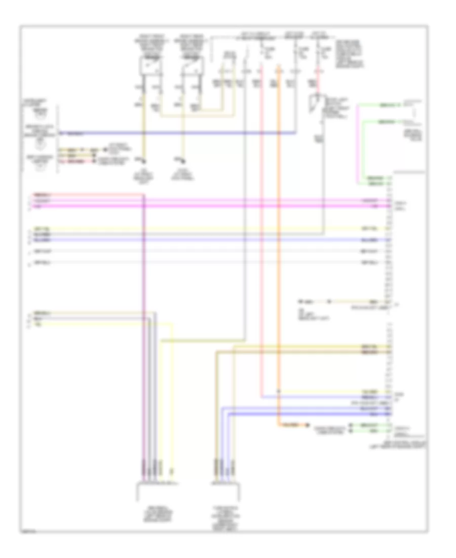
Anti-lock Brakes Wiring Diagram (2 of 2) for Mercedes-Benz E500 4Matic 2006
List of elements for Anti-lock Brakes Wiring Diagram (2 of 2) for Mercedes-Benz E500 4Matic 2006:
- (at right kick panel) w15/1
- (pin 15-28 not used)
- (pin 24-48 not used)
- (right front brake assembly) right front brake pad contact sensor
- (right rear brake assembly) right rear brake pad contact sensor
- Abs ind
- Brake fluid & parking brake warning ind
- Can h
- Can l
- Can-c h
- Can-c l
- Computer data lines system
- Diag
- Driver side sam control module with fuse & relay module (left rear of engine compt)
- Esp control module (left rear of engine compt)
- Esp warning lamp ind
- Fuse 10a
- Fuse 20a
- Fuse 7.5a
- Hot at all times
- Hot in on or start
- Hot w/ circuit 87 relay energized
- I13
- Instrument cluster
- Nca
- Sbc pedal value sensor (left rear of engine compt)
- Solid state
- Sps (pml) solenoid valve
- Stop light switch (left front upper footwell)
- Turn rate & lateral acceleration sensor (under right front seat)
- W15/1 (at right kick panel)
- W2 (at right headlight unit)
- W9 (at left headlight unit)