ANTI-LOCK BRAKES
Anti-lock Brakes Wiring Diagram (1 of 2) for Mercedes-Benz E550 2007

List of elements for Anti-lock Brakes Wiring Diagram (1 of 2) for Mercedes-Benz E550 2007:
- (-)
- (left rear of engine compt) esp/sps/bas control module
- (right front of engine compt) w3/1
- 12v
- All wheel drive
- Bla
- Bls
- Can-c h
- Can-c l
- Can-s h
- Can-s l
- Computer data lines system
- Df hl_m
- Df hl_s
- Df hr_m
- Df hr_s
- Df vl_m
- Df vl_s
- Df vr_m
- Df vr_s
- Diag
- Except all wheel drive
- Front axle inlet solenoid valve
- Front axle pre pressure sensor
- Front axle switchover solenoid valve
- Front prefuse (right front footwell)
- Fuse 40a
- High pressure charging pump
- Hot at all times
- Left front inlet control valve
- Left front outlet control valve
- Left front pressure sensor
- Left front wheel speed sensor (left front wheel)
- Left rear inlet control valve
- Left rear outlet control valve
- Left rear pressure sensor
- Left rear wheel speed sensor (left rear wheel)
- Nca
- Pml_12v
- Pml_a
- Rear axle inlet solenoid valve
- Rear axle switchover solenoid valve
- Rear sam control module w/ fuse & relay module c2 (left side of trunk)
- Right front inlet control valve
- Right front outlet control valve
- Right front pressure sensor
- Right front wheel speed sensor (right front wheel)
- Right rear inlet control valve
- Right rear outlet control valve
- Right rear pressure sensor
- Right rear wheel speed sensor (right rear wheel)
- Sps (pml) solenoid valve (if equipped)
- Traction system hydraulic unit
- W3/1 (right front of engine compt)
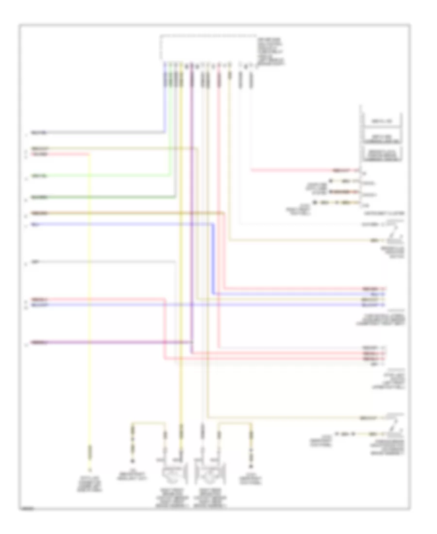
Anti-lock Brakes Wiring Diagram (2 of 2) for Mercedes-Benz E550 2007
List of elements for Anti-lock Brakes Wiring Diagram (2 of 2) for Mercedes-Benz E550 2007:
- 31e
- Abs mil ind
- Brake fluid & parking brake warning lamp ind
- Brake fluid indicator switch
- Can b h
- Can b l
- Computer data lines system
- Data link connector (under left side of dash)
- Driver side sam control module w/ fuse & relay module (left rear of engine compt) c1
- Esp & abs warning lamp ind
- I13
- Instrument cluster
- Nca
- Parking brake indicator switch (on parking brake assembly)
- Right front brake pad contact sensor (right front brake assembly)
- Right rear brake pad contact sensor (right rear brake assembly)
- Stop light switch (left front upper footwell)
- Turn rate & lateral acceleration sensor (under right front seat)
- W15/1 (near right kick panel)
- W15/1 (right front footwell)
- W2 (behind right headlight unit)